15
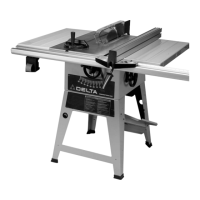
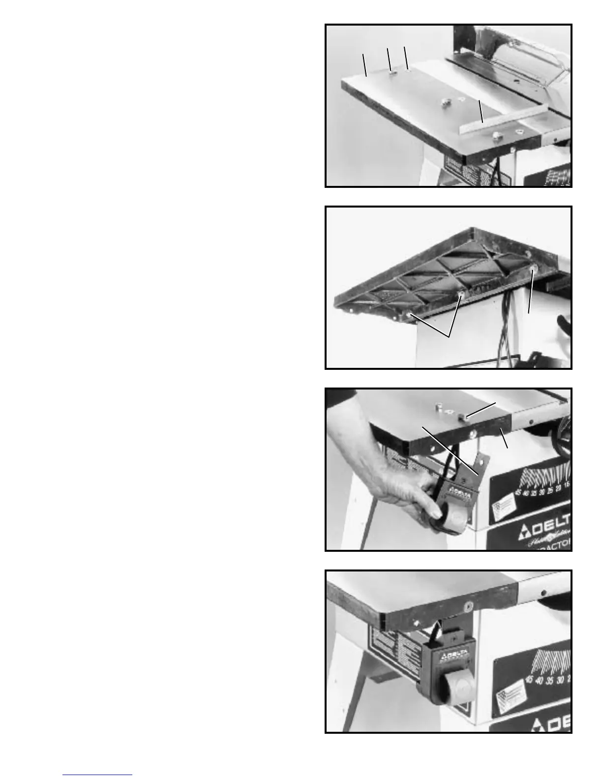
Fig. 37
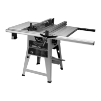
Fig. 38
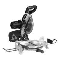
Fig. 39
ASSEMBLING
EXTENSION WING
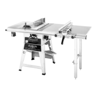
1. Assemble extension wing (A) Fig. 36, to the saw
table using three 7/16-20 x 1-1/4 † screws (B) and lock-
washers (C) as shown in Fig. 37.
ASSEMBLING SWITCH
TO EXTENSION WING
1. Assemble switch (A) Fig. 38, behind the lip of exten -
sion wing (B) with 1/4-20 x 3/4 † flat head screw (C), flat
washer, and locknut.
2. Fig. 39, illustrates the switch assembled to the exten -
sion wing.
2. W ith a straight edge (D) Fig. 36, make certain the
extension wing (A) is level with the saw t able before
tightening three screws (B) Fig. 37.
Fig. 36
C
B
A
D
B
B
A
C
B
 Loading...