13
Fig. 28
Fig. 29
Fig. 30
Fig. 31
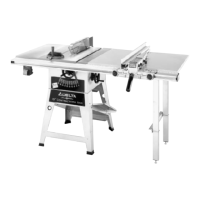
5. If an alignment is necessary, loosen the two screws
(F) Fig. 28, align bracket (D) with the arbor flange (E) and
tighten screws (F).
6. Loosely assemble large washer and screw (C) Fig. 28,
to the inside splitter bracket. This screw and washer was
removed in STEP 3.
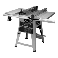
7. Assemble the blade guard and splitter assembly (G)
Fig. 29, between the large washer (C) and the splitter
bracket and tighten screw (H) with wrench supplied.
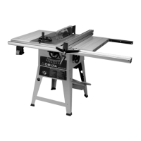
8. Fasten the rear of the blade guard and splitter bracket
assembly (G) Fig. 30, to the rear splitter mounting
bracket using 5/8 † carriage bolt (J) , flat washer , and hex
nut. IMPORTANT:The splitter (G) Fig. 30, has a notch
(L) cut in the top edge as shown. This feature will enable
the blade guard to st ay in the raised position to make
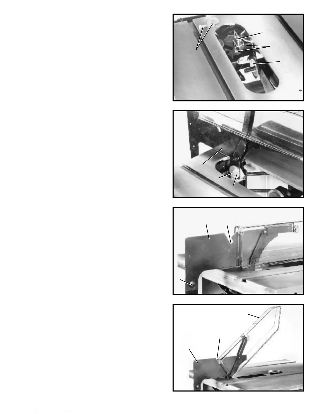
blade changing a little easier. Simply raise the front of
blade guard (M) Fig. 31, until the rear edge of the blade
guard slip s into notch (L) of splitter (G); the blade guard
will st ay in this position.
C
D
F
G
H
C
G
L
J
G
L
M
E
 Loading...