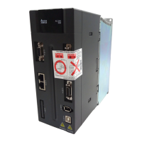
What to do if write parameter error occurs: read only on Delta Servo Drives?
- JJamie BaileyAug 27, 2025
If the parameter is read only, correct the PR command and parameter setting value.
What to do if write parameter error occurs: read only on Delta Servo Drives?
If the parameter is read only, correct the PR command and parameter setting value.
What to do if write parameter error occurs: exceeds the limit of normal range on Delta ASDA-A2 Servo Drives?
If the parameter setting value exceeds the limit of normal range, correct the PR command and parameter setting value.
What to do if data range error occurs when accessing CANopen PDO object on Delta ASDA-A2 Servo Drives?
If the data in the message has exceeded the data range of the specified object, NMT Maser send “Reset node“ command to its slave or reset the fault by sending the control word (0x6040) through CAN communication (the value of CANopen object 0x6040 should be reset).
What causes encoder initial magnetic field error in Delta Servo Drives?
If your Delta Servo Drives are showing an encoder initial magnetic field error, it means that the magnetic field of the encoder U, V, W signal is in error. If the error does not clear after each checking is done, please contact your distributor for assistance or contact with Delta.
How to resolve write parameter error parameter lock in Delta ASDA-A2?
To resolve a write parameter error in Delta Servo Drives due to a parameter lock, where the parameter is write-protected when Servo On or the setting value is invalid, correct the Pr command and parameter setting value.
What causes a reverse limit switch error on Delta ASDA-A2?
A reverse limit switch error on Delta Servo Drives can be triggered by: * The reverse limit switch being activated. If this is the case, activate reverse limit switch. * An unstable servo system. If this is the case, modify parameter setting and re-estimate motor capacity.
What to do if Delta ASDA-A2 show Encoder temperature exceeds the protective range?
If your Delta Servo Drives are showing that the encoder temperature exceeds the protective range, above 105?, improve heat dissipation or reduce the loading of operation.
What does 'Forward Limit Error' mean on Delta ASDA-A2 Servo Drives?
A forward limit error on Delta Servo Drives indicates: * The forward limit switch is activated: Enable the forward limit switch. * The servo system is unstable: Re-adjust the parameter or evaluate the motor capacity.
What does it mean when my Delta Servo Drive has a memory error?
A memory error on your Delta Servo Drive can occur due to: * Parameter data error when writing into EE-PROM. If this is the case, correct the setting value of the parameter to clear the fault and restart the servo drive. * The setting value of a hidden parameter is in error. If this fault occurs when resetting the parameter settings, it indicates that the servo drive type is not set correctly. Correctly set the servo drive type again. * Data in EE-PROM is damaged. If this is the case, please contact your distributor or Delta for assistance.
What causes excessive deviation in Delta ASDA-A2?
Excessive deviation in Delta Servo Drives can be caused by: * Maximum deviation parameter setting is too small. If this is the case, increase the parameter setting value of P2-35. * Gain value is too small. If this is the case, correctly adjust gain value. * Torque limit is too low. If this is the case, correctly adjust torque limit value. * There is an overload. If this is the case, reduce external applied load or re-estimate the motor capacity.
Enclosure Rating | IP20 |
---|---|
Control Mode | Position, Speed, Torque |
Communication Interface | RS-485, CANopen |
Protection | Overcurrent, Overvoltage, Undervoltage, Overload, Overtemperature, Encoder error |
Operating Temperature | 0°C to 55°C |
Storage Temperature | -20°C to 65°C |
Humidity | 20% to 90% RH (non-condensing) |
Altitude | 1000m max |
Cooling Method | Natural cooling or forced air cooling |
Encoder Feedback | 20-bit incremental encoder (standard), 17-bit absolute encoder (optional) |
Pre-operation checks for product condition and functionality.
Nameplate information and detailed model code explanation for ASDA-A2 and ECMA series.
Matching specifications for servo drives and motors across different voltage series.
Identification and function of various parts of the servo drive.
Important notes on connections, voltage, and wiring.
Environmental conditions required for installing the servo drive and motor.
Guidelines for correct mounting and ventilation space.
Recommended circuit breakers and fuses for various series.
Recommendations for EMI filters and installation precautions.
Guidelines for selecting regenerative resistors.
Wiring information for 220V series servo drives.
How to connect external devices to the servo drive.
Detailed description of servo drive connectors and terminals.
Wiring methods for single-phase and three-phase power.
Specifications for motor power cables.
Specifications for encoder cable connectors.
Wiring information for 400V series servo drives.
How to connect external devices to 400V series drives.
Detailed description of 400V series drive connectors and terminals.
Wiring methods for 400V series servo drives.
Basic wiring diagrams for 220V and 400V series.
Details on connecting I/O signals to the CN1 connector.
Pinout and layout of the CN1 connector.
Explanation of signals for the CN1 connector.
Details on the CN2 connector for motor encoder connection.
Information on wiring the CN3 connector for communication.
Details on the CN4 serial connector for PC connection via USB.
Information about the CN5 connector for full-closed loop applications.
Details on the CN6 connector for CANopen communication.
Standard wiring examples for the 220V series.
Standard wiring examples for the 400V series.
Detailed explanation of the servo drive's front panel components and their functions.
Step-by-step guide for setting parameters using the front panel.
Explanation of various status indicators and displays on the panel.
General operational functions accessible via the panel.
Pre-operation checks on the motor and drive without load.
Correct procedure for applying power to the servo drive.
Procedure for testing motor operation in JOG mode without load.
Steps for trial running the motor in speed mode without load.
Steps for trial running the motor in position mode without load.
General procedure for tuning the servo system.
Description of single, dual, and multi-control modes.
Detailed explanation of position control mode.
Detailed explanation of speed control mode.
Detailed explanation of torque control mode.
Explanation of dual mode operations.
Overview of the motion control capabilities of the ASDA-A2 series.
Information about system parameters, monitoring variables, and data arrays.
Explanation of the different motion axes and their attributes.
Detailed description of the PR (Procedure) mode.
How to perform homing operations in PR mode.
Overview of parameters related to motion control and PR mode settings.
Detailed explanation of the Electronic Cam (E-Cam) function.
Explanation of parameter grouping and naming conventions.
A comprehensive list of parameters, their abbreviations, functions, and related sections.
Detailed descriptions of various parameters, categorized by group.
List of servo drive alarms, their descriptions, corresponding DO signals, and servo status.
Troubleshooting for CANopen communication alarms and corrective actions.
Troubleshooting for motion control related alarms and corrective actions.
Detailed breakdown of common causes and corrective actions for various alarms.
General corrective actions for various alarm codes.