ASRTU-EC16AP1TA EtherCAT Remote Communication Module Operation Manual
6-20
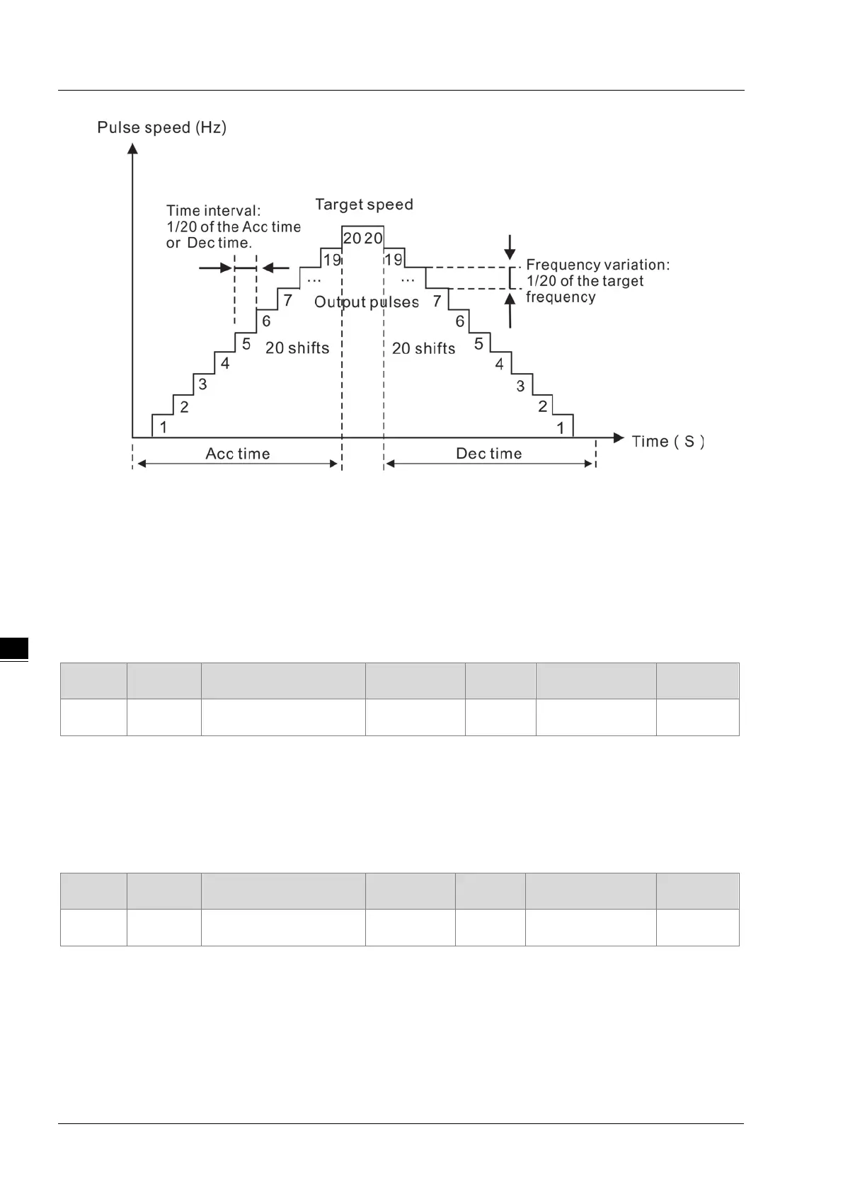
As shown in the figure above, when the acceleration time and deceleration time are both not 0, there are 20
steps respectively for the acceleration and deceleration of the pulse output. The output frequency increases
or decreases by 1/20 of the target frequency every step, with the unit: Hz, and the time for each step is 1/20 of
the acceleration time or deceleration time with the unit: ms.
In PWM mode, this parameter stands for the pulse output width, with the unit: us.
6.4.4.8 Pulse Output Channel 1 Deceleration Time (3005: 09h)
The parameter is the deceleration time or pulse output cycle for pulse output channel 1. Modifying the
parameter value is invalid after the pulse output is enabled except that the motion mode is set to PWM mode.
Index Subindex Name Data type Attribute
Supports PDO
mapping or not?
Default
3005h 9
Pulse output channel 1
Deceleration Time
UDINT RW YES 0
In speed output mode or position output mode, the parameter means the deceleration time for reaching the
target output frequency, with the unit: ms. In PWM mode, the parameter is the pulse output cycle with the unit:
us.
6.4.4.9 Pulse Output Channel 1 OutputMode (3005: 0Ah)
The parameter is available to set the output mode for pulse output channel 1. There are three output modes:
“pulse + direction”, “phase A + phase B” and “CW/CCW” for option.
Index Subindex Name Data type Attribute
Supports PDO
mapping or not?
Default
3005h A
Pulse output channel 1
OutputMode
USINT RW YES 0