SERVICE MANUAL
Checkout and adjustment
RTG PLUS (120V) (Rev. 0)
7-14
5. Press the X-ray button and check that the voltage is 10V ± 1V. If not,
adjust the R2 resistor collar of the board A1; moving the cursor to
the top, the anodic current value will increase, moving to the bottom
will decrease. Once the regulation is complete, tighten the screw on
the resistor collar.
NOTE:
The arm can be rotated to the desired position by pushing the “T” (31)
button; before rotating the arm, make sure that the lock (129 of Figure
7-4) is unlocked. When the arm reaches the position, push the X-ray
button (42).
6. After the adjustment, set the S1 switch back to its initial position.
7. To return to the normal working condition, access the set-up
programs and change S4 back to OFF.
8. Switch OFF the unit, switch it back ON, activate set-program (see
paragraph 7.2), press “s” (39) then "T" (31) several times until
reading S4 ON. Press “s” (39) to change S4 to OFF.
NOTE:
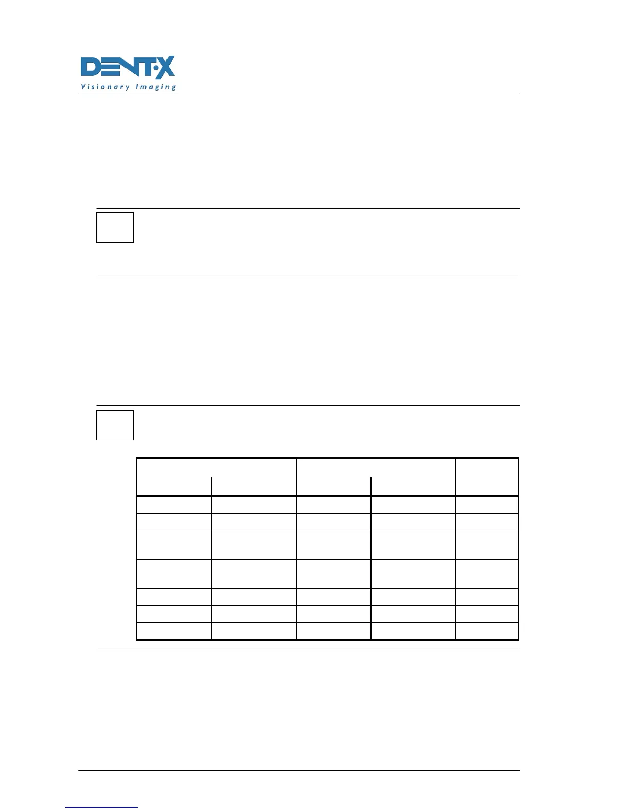
The 10mA anodic current value is the optimum value for the following
combinations between film and intensifying screens (green type).
Intensifying screens Films
Type Supplier Type Supplier
mA
setting
KR II KONIKA MG KONIKA 10
KR II KONIKA MGH KONIKA 10
Lanex
Regular
KODAK T-MAT G/RA
KODAK 10
Curix Ortho
Regular
AGFA T-MAT G/RA
KODAK 10
T 16 3M / IMATION XDA 3M / IMATION 10
Medium AGFA HTA AGFA 10
G8 FUJI HR-G FUJI 10
*
*