SERVICE MANUAL
Checkout and adjustments
(Rev. 0) RTG PLUS (120V)
7-19
7.5.2
7.5.27.5.2
7.5.2
Centering of the X
Centering of the XCentering of the X
Centering of the X-
--
-ray beam for the CEPH mode
ray beam for the CEPH moderay beam for the CEPH mode
ray beam for the CEPH mode
To check the alignment of the X-ray beam in the Teleradiography mode
proceed as follows:
1. Check that S4 is in OFF (see paragraph 7.2) position and that the
unit is prearranged for CEPH. If not proceed as described on the
paragraph 6.3.
2. Insert the film holder cassette centered on the film holder in the
position according to the type of the present diaphragm.
3. Perform an exposure at 60 kV for 0.80 sec. then develop the film.
4. Check that the film has a white edge all the way around as
established by the international standard concerning protection
against radiations (see following tables).
In case the white edge is missing on the horizontal side, and a rough
adjustment is required, adjust the two screws 123 of Figure 7-3 of the
diaphragm support.
If the required adjustment is small, adjust the screw 125.
In the case the white edge is missing on a vertical side, proceed to adjust
the end travel micro S2; be careful since the slightest deplacement of the
microswitch could make a large variation in the X-ray projection.
Moreover due to the microswitch S2 displacement it will be necessary to
proceed to a new adjustment of the arm check pin (129) by means of the
screws 131 and 130 (see Figure 7-4).
WARNING:
This setting requires, later on, the adjustment of the 0° degree position,
as described by the procedure of paragraph 7.2.4.
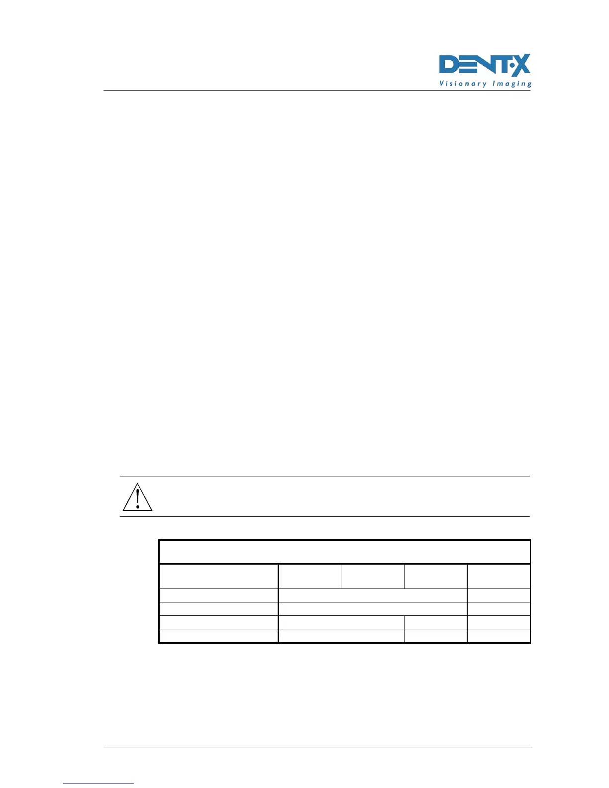
FORMATS IN INCHES
Diaphragme sizes
8"x10"
symm
8"x10"
asymm
10"x8"
asymm
12"x10"
symm
Film sizes 8"x10" 10"x12"
Film nominal size 201x252 252x302
X-ray beam height 225÷250 180÷200 225÷250
X-ray beam width 180÷200 225÷250 275÷300