SERVICE MANUAL
Checkout and adjustment
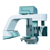
RTG PLUS (120V) (Rev. 0)
7-42
7.8.3
7.8.37.8.3
7.8.3
Memory data corrupted. Call Technical Assistance
Memory data corrupted. Call Technical AssistanceMemory data corrupted. Call Technical Assistance
Memory data corrupted. Call Technical Assistance
With the system on and this failure message displayed operate in
sequence on the small size push button (37), child (34) and TMJ1 (29)
(as per the SET-UP mode) wait 5 sec.: the operating condition should be
restored.
Should, after 5 seconds, the situation not be restored replace the CPU
(A2) PCB and thereafter proceed to the system general checking.
WARNING:
In any case, the factory and/or custom parameters are lost. Proceed to
insert all data, according to the one recorded on the “Final Test Table”
(see the last page of the User’s Manual) as described on the Set-up
procedure (see paragraph 7.2 and following).
7.8.4
7.8.47.8.4
7.8.4
"NO ANSWR"
"NO ANSWR""NO ANSWR"
"NO ANSWR"
This message can be read in three different circumstances following the
ignition phase of the system.
In the first case it can be read during the phase of the CPU A2 PCB
CHECK CONTROL (which is automatic during the system ignition phase)
and is tested by the lighting of LED H1 located between the components
D7 and D9 of the PCB itself; proceed in this case to replace the CPU (A2)
PCB and then proceed with the system general checking.
In the second case, the message can be read during the hand control
CHECK CONTROL phase (automatic as above); proceed in this case to
replace the hand control and then proceed with the system general
checking.
In the third case, the message can be read if transmission protocol has
failed and then no exchange of information between the hand control
and the CPU (A2) PCB is active.
Check, then, that the two female connectors of the coiled telephone cable
are well connected to the hand control and to the CPU PCB and that
there is continuity at the cable ends.
Should these checkings have a negative result, replace the hand control
or the CPU PCB in order to identify the origin of the failure.
After having replaced one of the two components proceed with the
system general checking.