SERVICE MANUAL
Checkout and adjustments
(Rev. 0) RTG PLUS (120V)
7-29
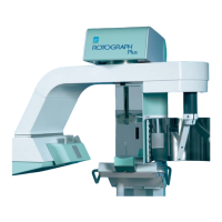
NOTE:
If you change one of the two values (A3) or (A4), it is recommended to
change also the other one of a corresponding opposite amount so as to
obtain a symmetrical exposure (see following diagram).
7. Press "s" (39) to display the string "A5 ......." (X-ray emission end
angle). This setting determines the end of emission which can be
modified of max of 2° with respect to the value indicated in the “Final
Test Table”.
This function will be used, for instance, in case of a anticipated stop
of X-ray emission that will cut the left condile.
NOTE:
To modify the darkening effect on the central area, change the V2 speed
by using the R40 trimmer of the A1 board.
To increase the darkening effect, decrease the motor speed by adjusting
the trimmer counterclockwise. To decrease the darkening effect, adjust it
clockwise.
Before adjusting the V2 voltage, you must read the voltage on the TP4 (+)
and TP3 (-) Test Points of the A1 power board and compare it to the one
indicated on the “Final Test table”. Now you may alter the voltage,
remembering that the value read cannot be changed of more than 1V.
V2 must always be lower than V1 of 3V ±
±±
±0.2V.
The R45 trimmer for the adjustment of the slope of the deceleration
ramp (deceleration from V1 to V2) located on the A1 board is
calibrated at the factory (3V/sec) and should not be adjusted on site.
*
A2
A3
A4
A5
A2
A3 → -3°
A4 → +3°
A5
*