GAVIN-6C Instruction Manual
- 12 -
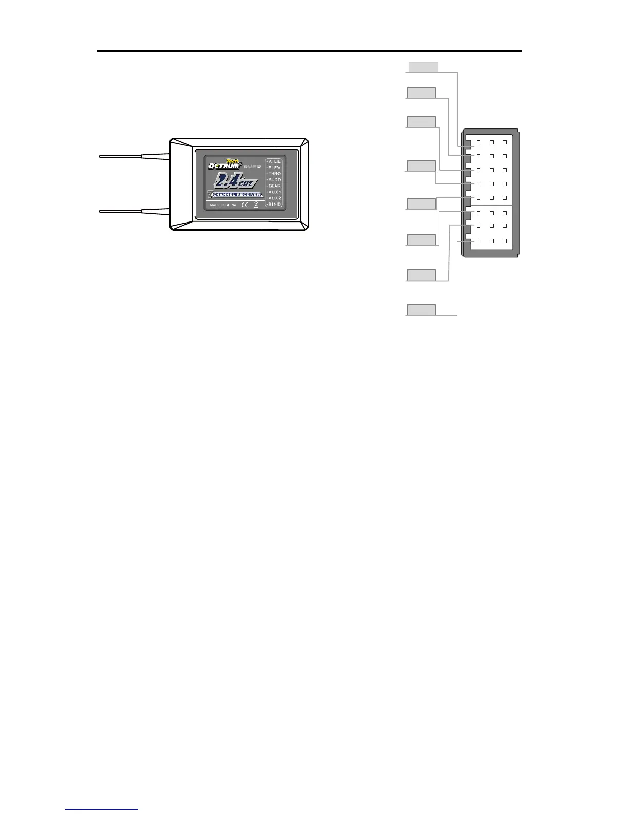
When connecting the servo to the channel connector, please note the line
sequence. Each connector has 3 pins, one of the pins near the front panel is the
signal end, and the remaining two pins are the positive and negative.
If the connectors become detached while flying, there will be a risk of
uncontrolled operation. Please securely insert all of the connectors as far as
they will go.
The two antennas of the receiver should be placed at 90 degrees to each
other. Do not place the two antennas twisted together or in parallel.