devolo dLAN® 200 AVpro Project Manual
14
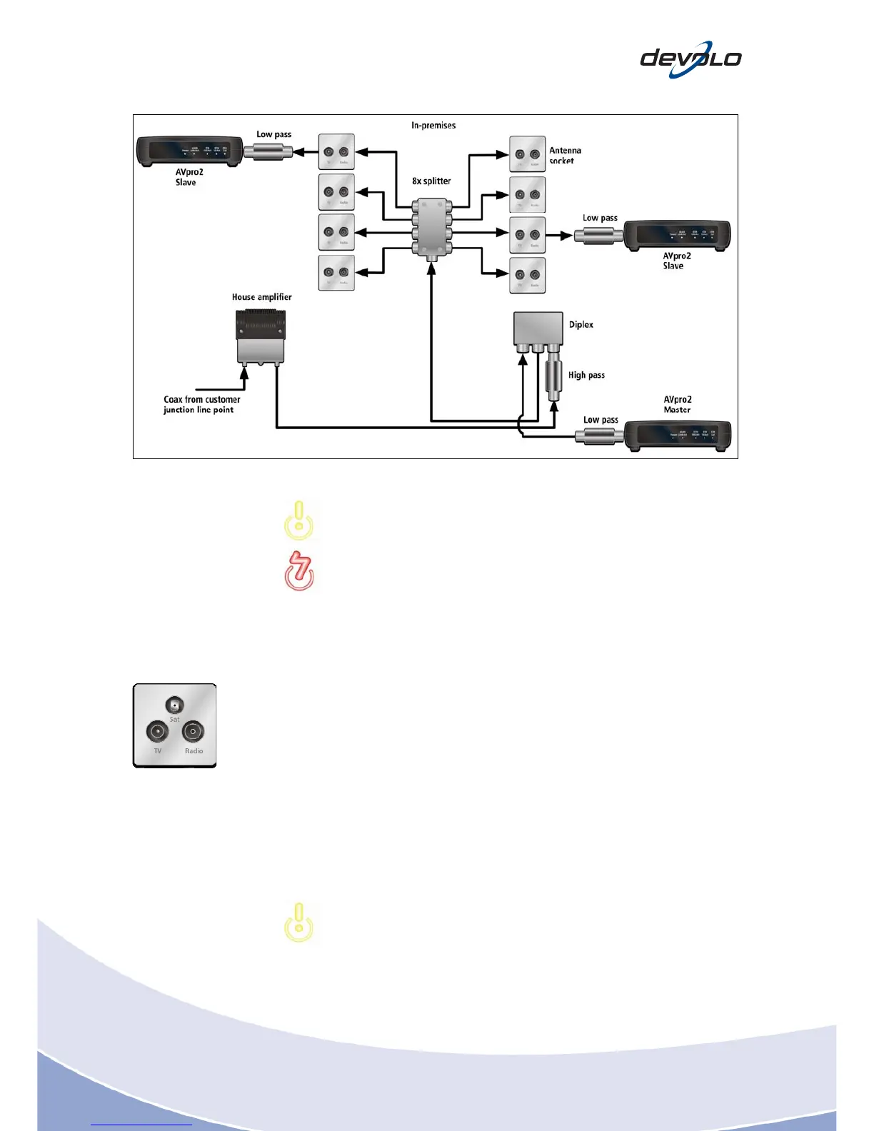
Fig. 3-10: Antenna system after connecting the adaptor over the antenna outlets
If the antenna distribution is connected to the local cable network, use a
high-pass filter at all times!
Wa
rning! The low-pass filter supplied in delivery (standard accessory: Part
No. 69723) should to be connected to the output on the dLAN unit at all
times to filter out ripples and hence prevent interference in the frequency
range for radio and TV.
3.5.2 Tapping the Ethernet signal on the antenna socket
You can tap th
e endpoints on the antenna socket outlet's radio output, if equipped
with one. This ouput is usually not allocated and the radio signal is less sensitive to
attenuation. If already allocated or not fitted to the antenna socket, you need to use
an additional T-piece, which causes additional attenuation of some 3.5 dB. If
multimedia sockets (socket outlets with 2 outputs for TV and radio, and an
additional F-connector output for data) are to be installed onsite, attach the
endpoint to the said data output. If no bandwidth or only a very small symmetrical
bandwidth is displayed, antenna sockets equipped with frequency converters with a
frequency range above 47 MHz may be installed, whereas attenuation takes place
below this at 20 - 30 dB. cf. Section 3.3.1).
In each of these case
s, we urgently recommend finding out the exact
component designation (e.g. ESD30) and researching the technical data on
the web. This will provide you with the frequency responses and
attenuation values.