EasyManuals Logo

DEWESOFT IOLITE Series User Manual

DEWESOFT IOLITE Series
101 pages
To Next Page IconTo Next Page
To Previous Page IconTo Previous Page
Page #30 background imageLoading...
Page #30 background image
IOLITE® 
TECHNICAL REFERENCE MANUAL
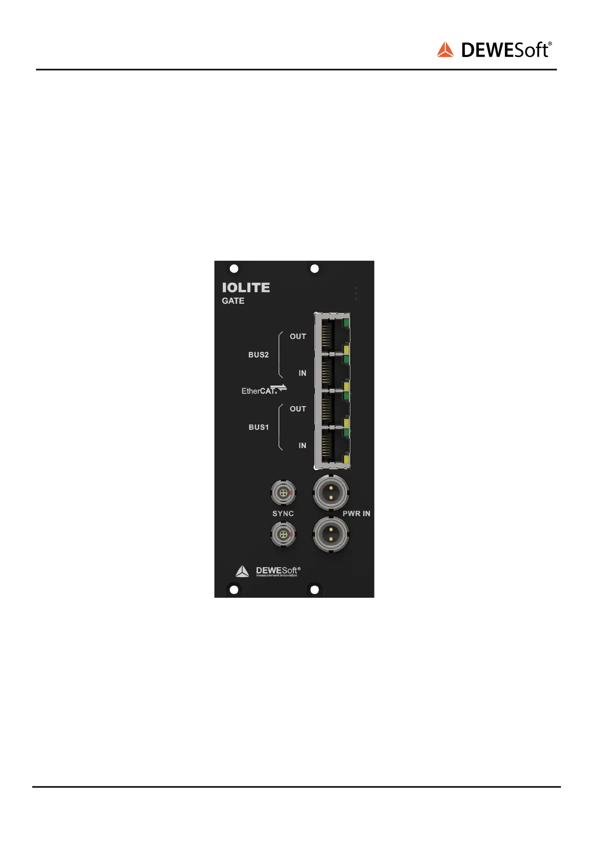
4.3.1.3.1. IOLITE-GATE: Connectors
The IOLITE-GATE module includes 4x RJ45 connectors for dual EtherCAT bus. Primary bus (BUS 1) for
buffered data and Secondary bus (BUS 2) for unbuffered data have IN and OUT connectors.
Two 2-pin LEMO 1B connectors are used for redundant power supply (PWR IN).
Synchronization with DEWESoft USB data acquisition devices or connection to clock master is on
IOLITE-GATE enabled by connecting a synchronization cable to two SYNC inputs (4-pin LEMO 00).
IOLITE-GATE f ront
IOLITE® V20-1 30 / 101

Table of Contents

Questions and Answers:

Question and Answer IconNeed help?

Do you have a question about the DEWESOFT IOLITE Series and is the answer not in the manual?

DEWESOFT IOLITE Series Specifications

General IconGeneral
BrandDEWESOFT
ModelIOLITE Series
CategoryControl Systems
LanguageEnglish

Related product manuals