EasyManuals Logo

DEWESOFT IOLITE Series User Manual

DEWESOFT IOLITE Series
101 pages
To Next Page IconTo Next Page
To Previous Page IconTo Previous Page
Page #32 background imageLoading...
Page #32 background image
IOLITE® 
TECHNICAL REFERENCE MANUAL
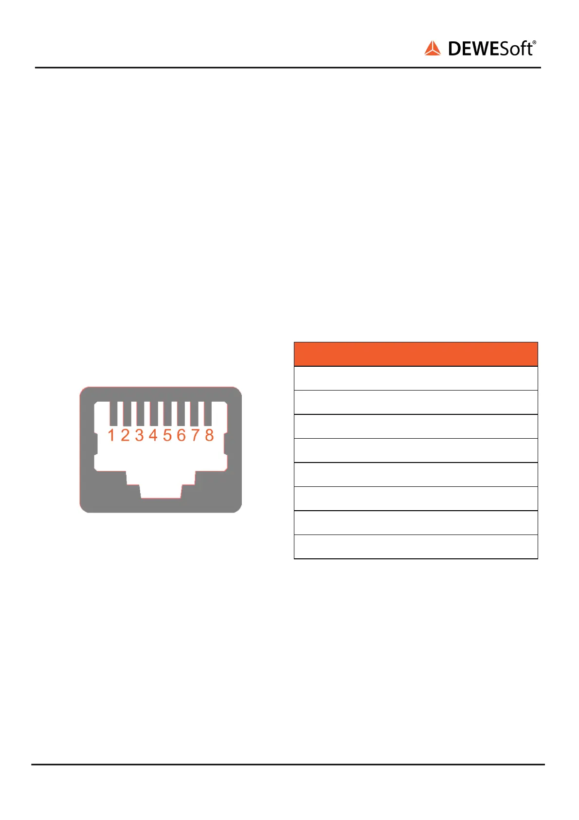
4.3.1.3.1.3. IOLITE-GATE: RJ45: Pinout
The IOLITE-GATE module includes four RJ45 connectors that enable data transfer and synchronization
via dual EtherCAT bus.
The same connectors are used on Primary bus (BUS 1) for buffered data and on Secondary bus (BUS 2)
for unbuffered data.
Each RJ45 connector has two LEDs:
- GREEN LED indicates that IOLITE is connected to another device (DEWESoft EtherCAT device, PC or
3rd party control master).
- YELLOW LED is active only when the data transfer is active.
Connector used on the device is a standard Ethernet connector (RJ45).
Standard ethernet cable with standard connector can be used to connect IOLITE-GATE with a PC.
EtherCAT connector: pin-out (RJ-45 female)
Pin
Name
Description
1
TX_P
Transmission +
2
TX_N
Transmission - 
3
RX_P
Reception +
4
-
-
5
-
-
6
RX_N
Reception -
7
-
-
8
-
-
IOLITE® V20-1 32 / 101

Table of Contents

Questions and Answers:

Question and Answer IconNeed help?

Do you have a question about the DEWESOFT IOLITE Series and is the answer not in the manual?

DEWESOFT IOLITE Series Specifications

General IconGeneral
BrandDEWESOFT
ModelIOLITE Series
CategoryControl Systems
LanguageEnglish

Related product manuals