IOLITE®
TECHNICAL REFERENCE MANUAL
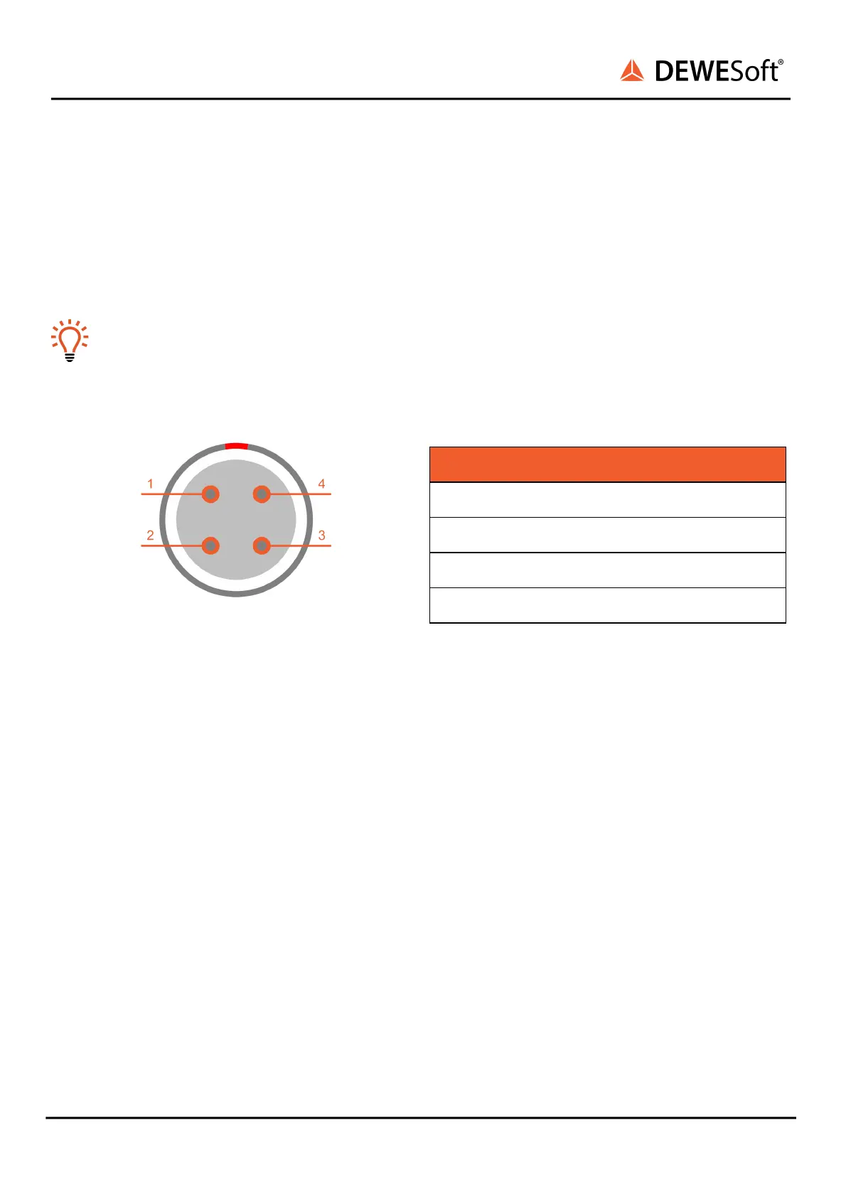
4.3.2.3.2. IOLITEs: Boxed Chassis: Sync: Pinout
The sync connectors are required when you want to synchronize the data from IOLITE with DEWESoft
USB devices for the same measurement. The signal that is transferred over sync cable makes sure that
the measurement data of IOLITE and DEWESoft USB devices are perfectly synchronized to each other.
The other use of a sync connector is to connect directly to IOLITE a signal from the clock master.
Hint
There is no distinction between the IN and OUT – it does not matter which connector you use.
When IRIG-synchronisation is used, the IRIG signal is on pins 1, 2.
SYNC connector (on the device): EEG.00.304.CLL
Mating connector (for the cable): FGG.00.304.CLAD27Z
IOLITE® V20-1 39 / 101