EasyManuals Logo

DEWESOFT IOLITE Series User Manual

DEWESOFT IOLITE Series
101 pages
To Next Page IconTo Next Page
To Previous Page IconTo Previous Page
Page #33 background imageLoading...
Page #33 background image
IOLITE® 
TECHNICAL REFERENCE MANUAL
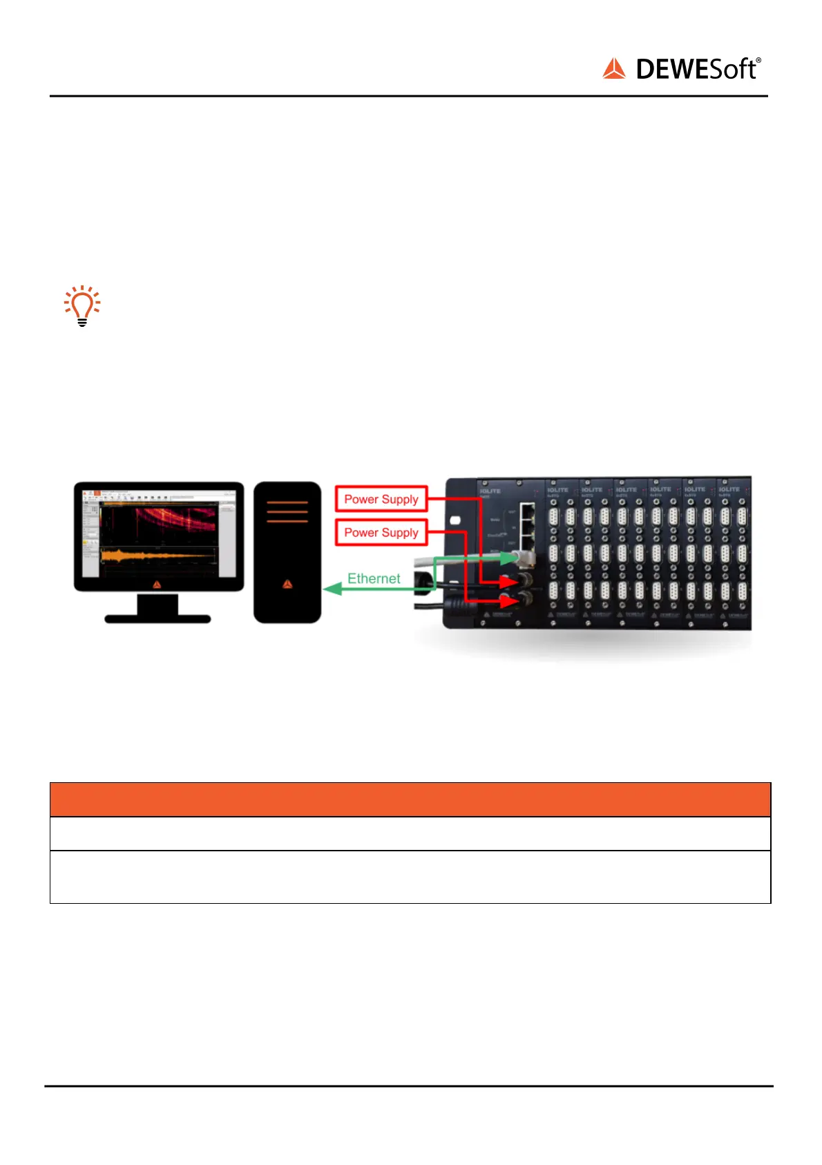
4.3.1.4. IOLITE-GATE: Connection of IOLITEr standalone device to PC
First connect the power supply cable (PS-120-L1B2f) to the PWR IN 2-pin LEMO 1B connector. To increase
system reliability connect the redundant power supply to other PWR IN connectors.
Hint
To improve the redundancy of the system, it is recommended that the device is powered with
two power supplies connected to different electrical fuses!
Then connect a standard ethernet cable to the IN connector of BUS 1 on IOLITE-GATE. Finally, connect
the other side of the ethernet cable to the LAN port of PC.
Connection of IOLITEr standalone device to PC
List of required cables:
Function
DEWESoft ORDER CODE
Power supply
PS-120-L1B2f (default)
Ethercat
CABLE-UTP-CAT.6-3m (default),
CABLE-UTP-CAT.6-1m
IOLITE® V20-1 33 / 101

Table of Contents

Questions and Answers:

Question and Answer IconNeed help?

Do you have a question about the DEWESOFT IOLITE Series and is the answer not in the manual?

DEWESOFT IOLITE Series Specifications

General IconGeneral
BrandDEWESOFT
ModelIOLITE Series
CategoryControl Systems
LanguageEnglish

Related product manuals