EasyManuals Logo

DEWESOFT IOLITE Series User Manual

DEWESOFT IOLITE Series
101 pages
To Next Page IconTo Next Page
To Previous Page IconTo Previous Page
Page #42 background imageLoading...
Page #42 background image
IOLITE® 
TECHNICAL REFERENCE MANUAL
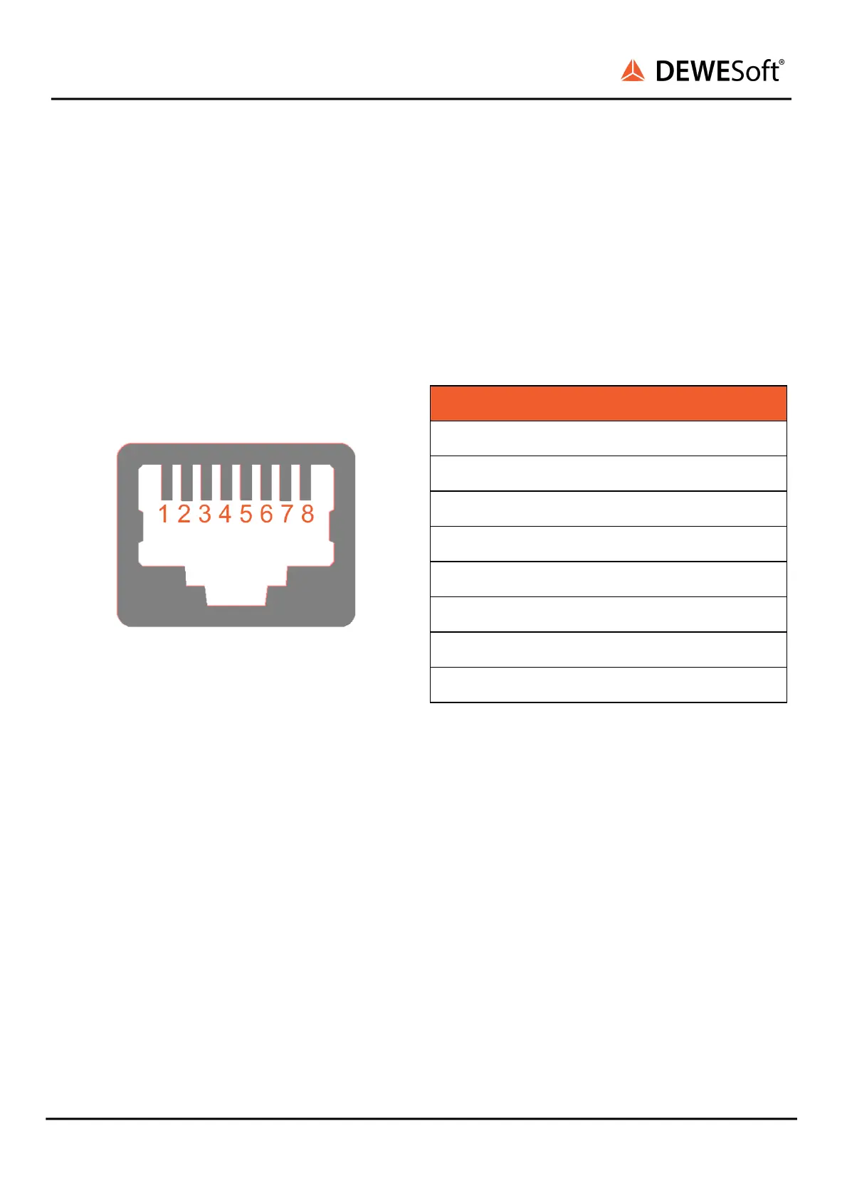
4.3.2.3.5. IOLITEs: Boxed Chassis: BUS 2: RJ45: Pinout
IOLITEs includes two RJ45 connectors on Secondary bus (BUS 2) for unbuffered data.
Each RJ45 connector has two LEDs:
- GREEN LED indicates that IOLITE is connected to another device.
- YELLOW LED is active only when the data transfer is active.
Connector used on the device is a standard ethernet connector (RJ45).
Standard ethernet cable with standard connector can be used to connect IOLITE-GATE with a PC.
EtherCAT connector: pin-out (RJ-45 female)
Pin
Name
Description
1
TX_P
Transmission +
2
TX_N
Transmission - 
3
RX_P
Reception +
4
-
-
5
-
-
6
RX_N
Reception -
7
-
-
8
-
-
IOLITE® V20-1 42 / 101

Table of Contents

Questions and Answers:

Question and Answer IconNeed help?

Do you have a question about the DEWESOFT IOLITE Series and is the answer not in the manual?

DEWESOFT IOLITE Series Specifications

General IconGeneral
BrandDEWESOFT
ModelIOLITE Series
CategoryControl Systems
LanguageEnglish

Related product manuals