DIGIPLEX CONTROL PANEL 11
doors and much more. For details on how to program the PGMs,
refer to section 11.
PGM1 provides a maximum 100mA output, PGM2 to PGM4
provide a maximum 50mA output and PGM5 is a relay output that
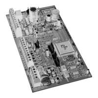
provides a maximum of 5A. If the current draw on the PGM is to
exceed the current output, we recommend the use of a relay as
shown in Figure 3-6. PGM1 to PGM4 are normally open outputs
and PGM5 is a normally open or normally closed 5A relay. Also,
note that PGM1 can be programmed as a 2-wire smoke detector
input. For more information, refer to section 3.15.1 and section
11.3 of this manual.
Figure 3-6: PGM Relay Output
3.10 BUS ZONE CONNECTIONS
The bus is a 4-wire communication bus that provides power and
two-way communication between the control panel and all modules
connected to it. All bus detectors, keypads and Digiplex modules
are connected to the bus, which can support up to 95 modules.
Connect the four terminals labeled RED, BLK, GRN and YEL of
each detector, keypad or module to the corresponding terminals of
the control panel as shown in Figure 3-3 on page 8. Please note
that all bus modules can be connected in a star and/or daisy chain
configuration. The final device on the communication bus should
not be more than 3000ft (914m) from the control panel. For
information on how to assign a detection device to a zone in the
control panel, please refer to Zone Programming on page16.
Before connecting a bus module to the control panel,
shutdown the control panel by removing AC and
battery power.
3.11 SINGLE ZONE CONNECTIONS
In addition to the bus, the Digiplex Control Panel includes four
hardwired input terminals for use with traditional hardwired (non-
bus) door contacts, smoke detectors and/or detectors. The control
panel also supports one on-board Expansion Module, the ZX4. The
ZX4 will add four hardwired input terminals to the control panel.
The ZX1 or ZX8 Zone Expansion Bus Modules can provide one or
eight additional hardwired input terminals when connected to the
bus. Devices connected to hardwired input terminals must be
assigned to a zone and the zone's parameters must be defined.
Please refer to Zone Programming on page16 for more
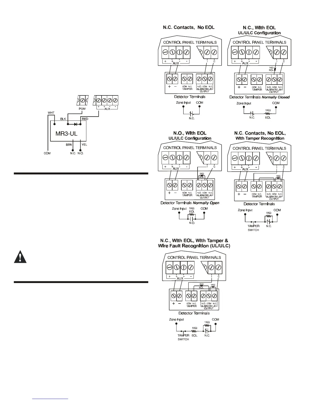
information. Figure 3-7 demonstrates single zone (ATZ disabled)
hardwire input terminal connections recognized by the Digiplex
system. For UL listed installations, use EOL resistor part
#2011002000.
Figure 3-7: Single Zone Input Connections