DIGIPLEX CONTROL PANEL 13
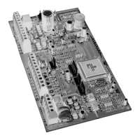
shown in Figure 3-10. Please note that you should avoid
connecting more than 20 ESL smoke detectors. When an ESL
smoke detector sends a CleanMe
TM
signal, the control panel will
generate a Zone Fault trouble and if programmed will transmit the
Fire Loop report code to the central station. The trouble will be
cleared if there is no CleanMe
TM
signal for 255 seconds. If an
alarm occurs, the trouble will be cleared until it is detected again.
Figure 3-10: PGM1 2-wire Smoke Detector Input
3.15.3 Smoke Detector Installation (4-Wire)
Connect the 4-wire smoke detectors and a relay as shown in
Figure 3-11. Recommended: The System Sensor model 2112/24D
smoke detectors. To comply with UL955, the 4-wire smoke
detectors must be installed using 18 gauge wire. In the event
power is interrupted, the relay will cause the control panel to
transmit the Fire Loop Trouble report if programmed in section
[707]. To reset (unlatch) the smoke detector after an alarm, verify
that the negative (-) of the smoke detector is connected to a PGM
as shown in Figure 3-11. Then program the PGM with the “Smoke
Reset” activation event (see section 11.1 of this manual) to
interrupt power to the smoke detector for four seconds when the
[CLEAR] and [ENTER] keys are pressed and held for two seconds.
Figure 3-11: Fire Zones
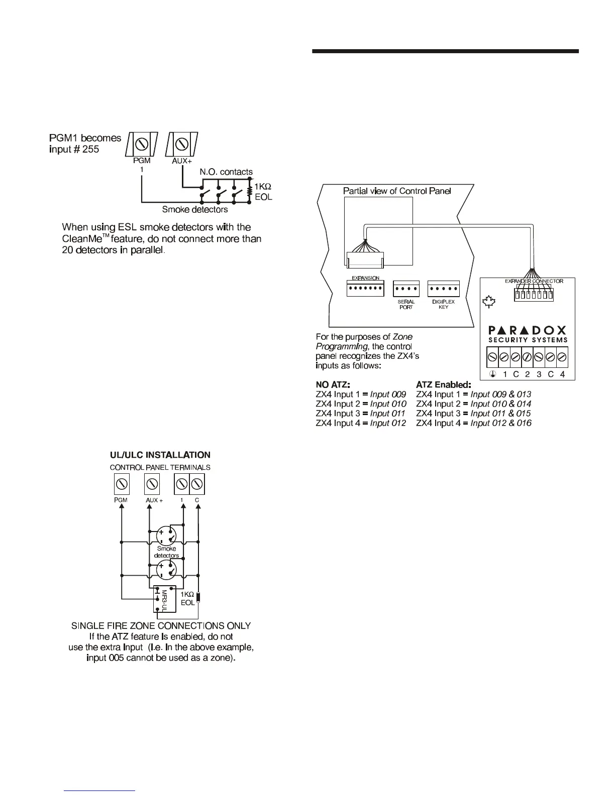
3.16 CONNECTING THE ZX4
The ZX4 is a 4-Zone Hardwire Expansion Module that connects
directly to the control panel through its on-board EXPANSION
connector as shown in Figure 3-12. It provides four additional
hardwired input terminals (8 zones with ATZ enabled). Connect
detection devices to the ZX4's terminals in the same way they are
connected to the control panel as shown in Figure 3-7 on page 11
or Figure 3-8 on page 12. Devices connected to hardwired input
terminals must be assigned to a zone and the zone's parameters
must be defined (see section 5).
Figure 3-12: Connecting the ZX4