DIGIPLEX CONTROL PANEL 49
Trouble [7]: Battery Failure
Module's battery is disconnected, needs to be recharged, or
replaced.
Trouble [8]: Supply Output
Module has exceeded current limits.
GROUP [4]: BUS TROUBLES
Trouble [1]: Missing Keypad
A keypad is no longer communicating with the control panel.
Trouble [2]: Missing Module
A device is no longer communicating with the control panel.
Trouble [5]: Safety Mismatch
A Safety Mismatch occurs when a locked module is installed on the
bus and its locking code does not match the control panel’s locking
code. During a Safety Mismatch Trouble, users will not be able to
arm. Remove the locked module to clear the trouble (its LED will
flash). V2.13 or higher.
Trouble [6]: General Failure
No communication between the devices and the control panel.
Trouble [7]: Bus Overload
Too many devices (over 95) are connected on the bus.
Trouble [8]: Bus Communication Error
The bus is having difficulty communicating between the devices
and the control panel.
GROUP [5]: ZONE TAMPER
The zone or zones that have been tampered with will be displayed.
GROUP [6]: ZONE LOW BATTERY
If a wireless device's battery needs to be replaced, the zone that it
is assigned to will be displayed. Also, the yellow light on the device
will flash when this trouble is occurring.
GROUP [7]: ZONE FAULT
A smoke detector is experiencing a wiring problem, needs to be
cleaned, or a wireless device is no longer communicating with its
receiver (supervision loss).
GROUP [8]: CLOCK LOSS
The time and date have been reset to the default. To set:
1) Press the [8] key
2) Enter the hour and minutes according to the 24-hour clock (i.e.
9AM is 09:00 and 9PM is 21:00).
3) Enter the correct date according to yyyy/mm/dd.
4) Press [CLEAR] to exit.
If the Access Control feature is enabled in the system and
the option Door Access during Clock Loss is ON (section
[537] option [8]), only the System Master Code and User
Codes with the Master feature enabled will be able to
program the clock. Enter the System Master or a Master
Code, press [TRBL], then continue with the steps above.
16.8 EVENT RECORD DISPLAY
The Event Record Display can only be viewed through an LCD
Keypad. The Event Record Display will record the user-initiated
actions that occurred in the system as well as any alarms or
troubles.
For example, when a valid code is entered, the User Access Code
and the action taken (arm, disarm, etc.) is recorded.
Access Control events can only be viewed through an
Access Control LCD Keypad (DGP-641ACC)
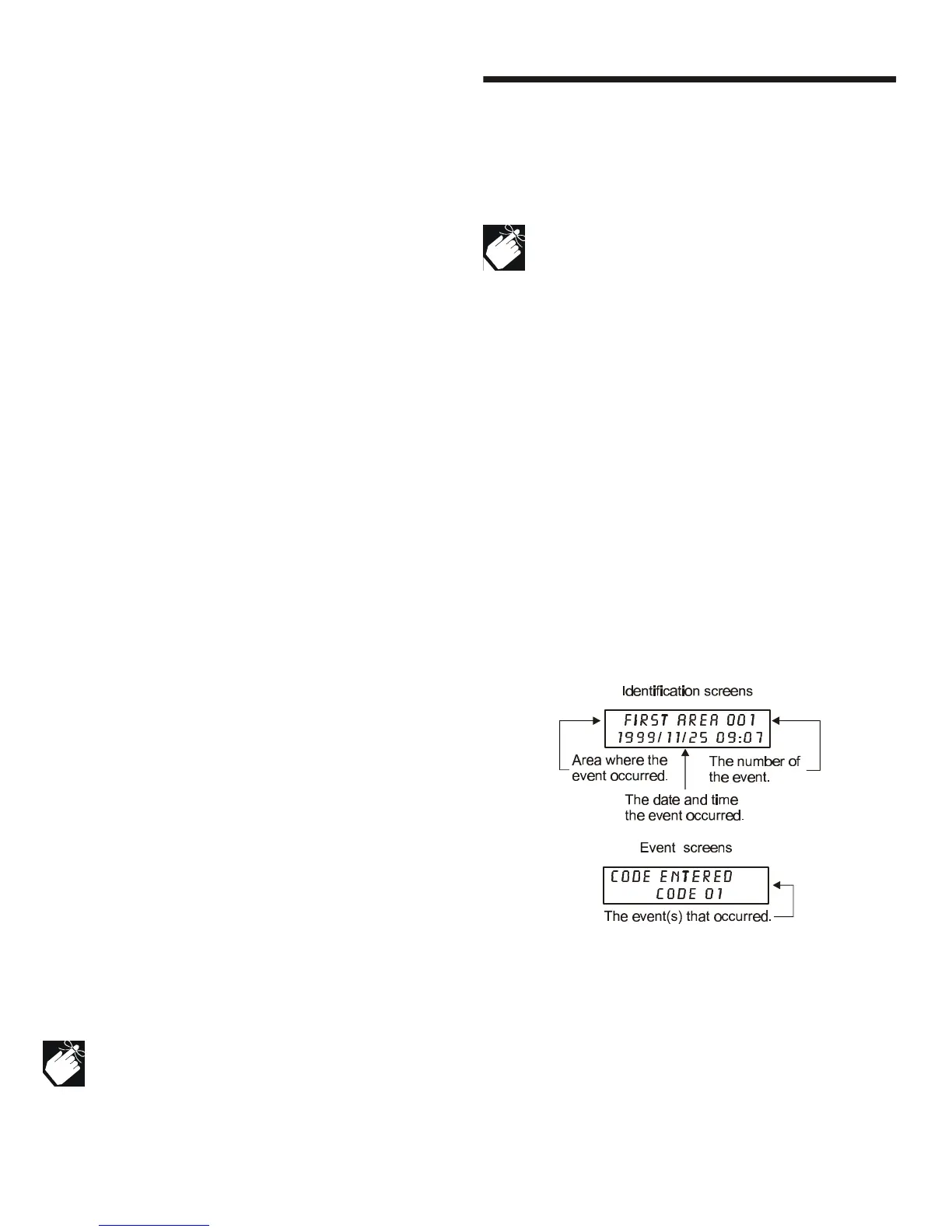
You have the choice of viewing the events in all the partitions at
once or by individual area. In either case the most recent event is
displayed first (see Figure 16-3: Event Record screens).
To view the events:
1) Enter the [SYSTEM MASTER CODE]
2) Press the [7] key
3) Press the [0] key for all partitions
Press the [1] key for Partition 1
Press the [2] key for Partition 2
Press the [3] key for Partition 3
Press the [4] key for Partition 4
4) Use the [q] key to view subsequent events
5) Press the [CLEAR] key to exit
Once you have entered the Event Record Display, you can change
the order that the Event Record screens (see Figure 16-3: Event
Record screens) appear by pressing the [7] key. If you already
know the number of the event you want to view, press the [MEM]
key and then enter the event's number.
Figure 16-3: Event Record screens