12 REFERENCE & INSTALLATION MANUAL
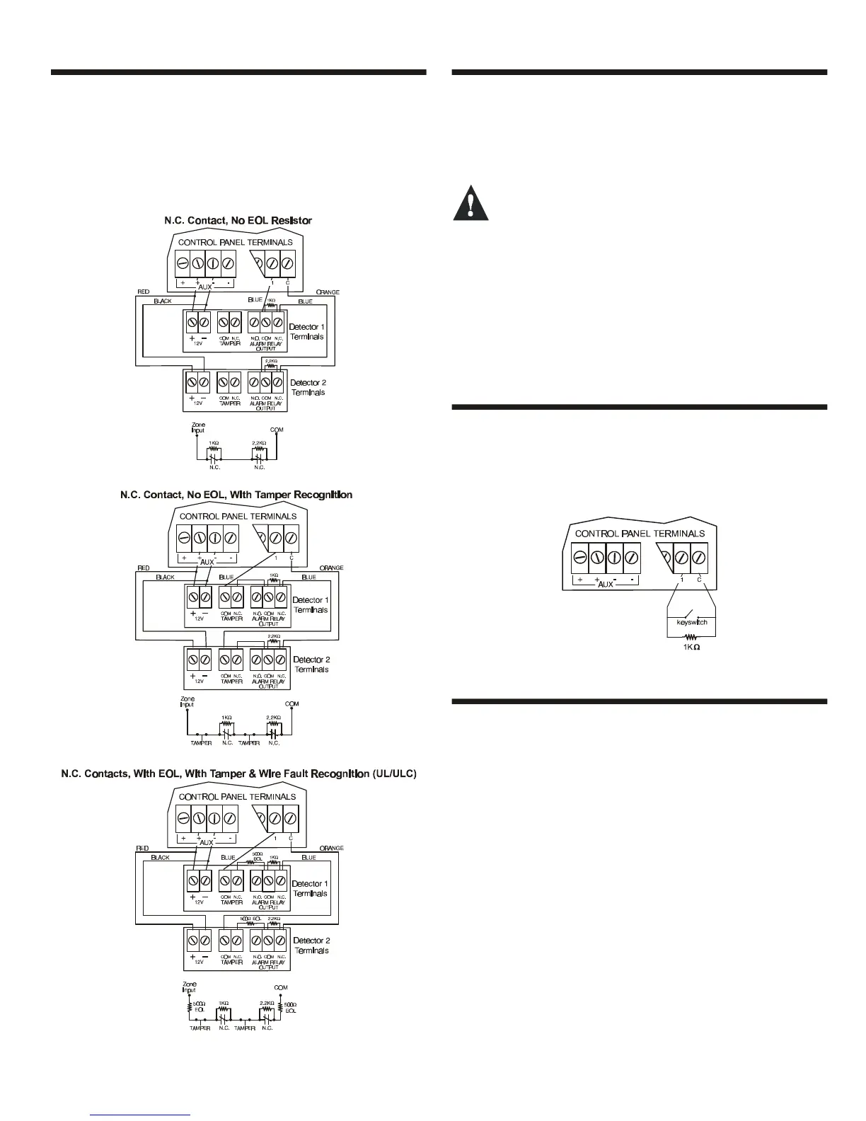
3.12 DOUBLE ZONE CONNECTIONS
Enabling the ATZ feature (see section 5.7) allows you to install two
detection devices per input terminal. The ATZ feature is a software
oriented feature. Simply connect the devices as shown in Figure 3-
8. Devices connected to input terminals must be assigned to a
zone and the zone's parameters must be defined. Please refer to
Zone Programming on page16 for more information. For UL listed
installations, use EOL resistor part #2011002000.
Figure 3-8: Double Zone Connections
3.13 KEYPAD ZONE CONNECTIONS
Each keypad has one hardwired input terminal allowing you to
connect a detector or door contact directly to the keypad. For
example, a door contact located at the entry point of an
establishment can be wired directly to the input terminal of the
entry point keypad instead of all the way to the control panel.
Even with the ATZ feature enabled in the control
panel, only one device can be connected to the
keypad’s hardwired input terminal. Tamper is not
recognized on keypad zones. The keypad zone follows
the control panel’s EOL definition.
A device connected to the keypad’s input terminal must be
assigned to a zone in the control panel and the zone’s parameters
must be defined (see Zone Programming on page16). The keypad
will communicate the status of the zone to the control panel via the
communication bus. The detection device is connected as shown
in Figure 3-3 on page 8.
3.14 KEYSWITCH CONNECTIONS
Connect the keyswitches to the keypad, control panel, or Zone
Expansion Module's hardwired input terminals as shown in Figure
3-9. Once a keyswitch is connected, it must be assigned a
keyswitch zone and its parameters must be defined as described in
Keyswitch Programming on page21.
Figure 3-9: Keyswitch Connections
3.15 FIRE CIRCUITS
Connect the smoke detectors used in the security system using
any of the following methods. Smoke detectors connected to the
control panel or zone expansion input terminals must be assigned
to a zone in the control panel and the zone's parameters must be
defined as a Fire Zone. For more details, refer to Zone
Programming on page16.
3.15.1 Smoke Detector Installation (2-Wire)
PGM1 can be defined as a 2-wire smoke detector input (see
section 11.3) enabling smoke detectors to be connected as shown
in Figure 3-10 on page 13. Fire Zones must use a 1kΩ EOL
resistor. If there is a line short or if the smoke detector becomes
active, whether the system is armed or disarmed, the control panel
will generate an alarm. If the line is open, the “Zone Fault” trouble
indication will appear in the Trouble Display and will transmit the
appropriate report code to the central station (if programmed).
3.15.2 ESL CleanMe
TM
Installation
The Digiplex control panel supports the use of ESL smoke
detectors that have the CleanMe
TM
feature. The ESL smoke
detectors are connected exactly like standard smoke detectors as