DIGITAL-LOGIC AG PCCP5 Manual V2.3
100
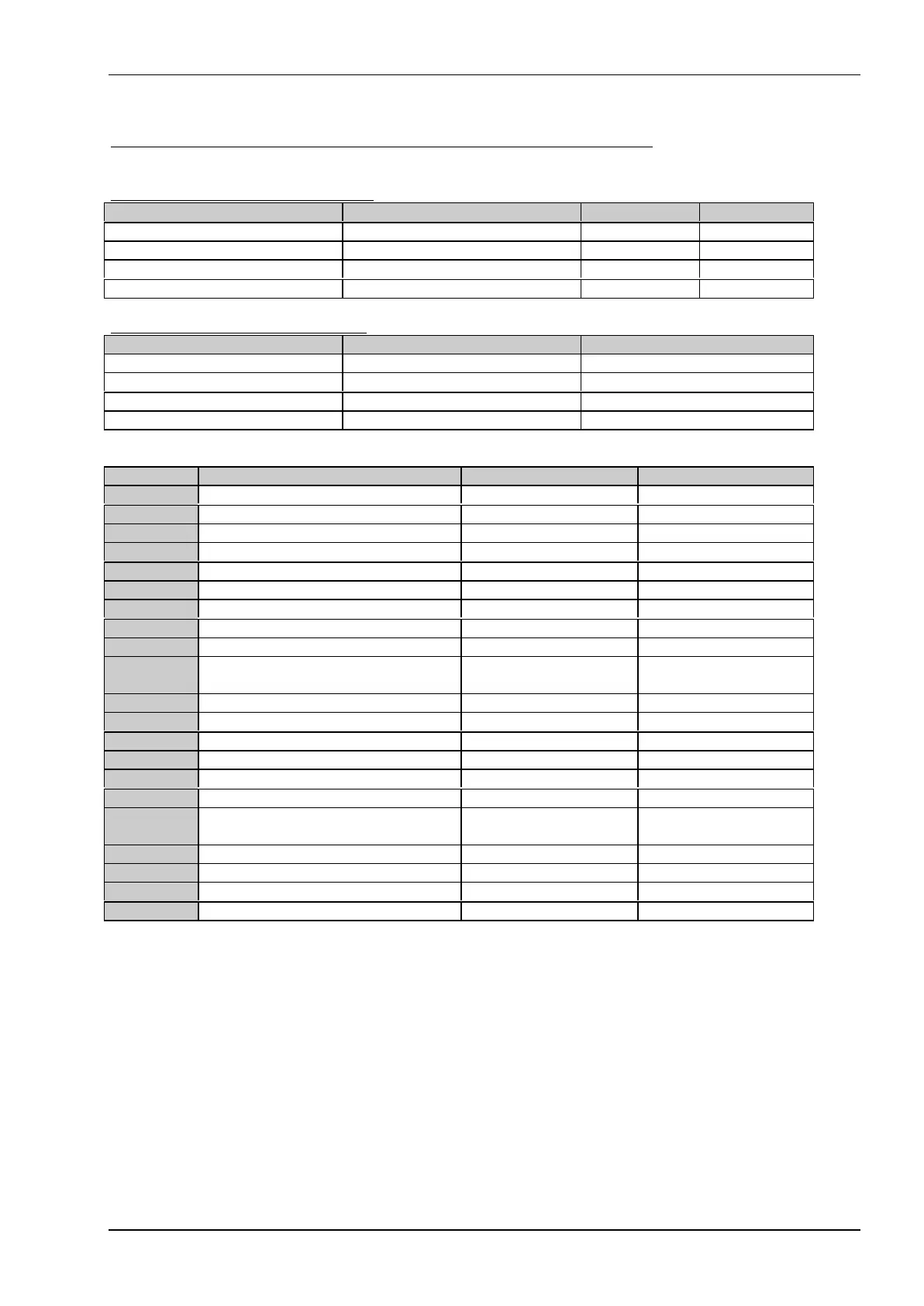
The jumpers on the top- and bottom- side of the PCC-P5, (solder jumpers)
Parallel Port Address (default LPT1)
PCF1 (RTS1) R54 ** PCF0 (TXD1) J16 ** Port address IRQ
low Low 1-2 Disabled 7
Low high 2-3 PS2 3BCh 7
High Low 1-2 LPT1 378h 7
High high 2-3 LPT2 278h 7
Parallel Port Mode (default normal)
ECPEN (MTR2) J15 ** PADCF (GAME) J14 ** Printer function
Low 1-2 Low 1-2 Std. Printer Port, output only
Low 1-2 High 2-3 Enh.Printer Port, bidirectional
High 2-3 Low 1-2 ECP
High 2-3 High 2-3 ECP & EPP
Jumper Signals 1-2 = open 2-3 = closed
J09 External SMI event open = enabled close = disabled
J12** Micro floppy drive select 1-2 = DRV B: 2-3 = DRV A:
J13** Micro floppy drive select 1-2 = DRV B: 2-3 = DRV A:
J45 Keyboard Data open = keymatrix closed = normal
J46 Keyboard Clk open = keymatrix closed = normal
J54 LCD Voltage select 1-2 = 5V LCD 2-3 = 3.3V LCD
J55 VDD Save voltage 1-2 = 12V 2-3 = 5V
J57 CTAG10 select (factory setting) 1-2 = to VIO 2-3 = to GND
J63 Source the RTC from 3.3V
for batteryless systems only
open
battery assembled
closed = low
batteryless
J68** Audio configuration (not used) open
J69** Audio configuration (not used) open
J78 VGA Power AVCC,IVCC, SVCC 1-2 = 5V 2-3 = 3.3V
J79 VGA Powersupply Bus BVCC 1-2 = 5V 2-3 = 3.3V
J80 VGA Powersupply Memory MVCC 1-2 = 5V Memory 2-3 = 3.3V Memory
J87 Memory supply, new since V2.2 1-2 = +5V 2-3 = 3.3V
J89 GPO0 mode,
not supported
open closed
J92 COM1 select RS232 RS422/485
J94 COM2 select RS232 RS422/485
J100 Audio configuration mode external standard
J101 Audio configuration mode EEPROM internal external
** only on old version PCC-P5 V2.1a
Settings written in bold are defaults!