DIGITAL-LOGIC AG PCCP5 Manual V2.3
99
5.1 Jumpers on this MICROSPACE product
Jumper locations on the board
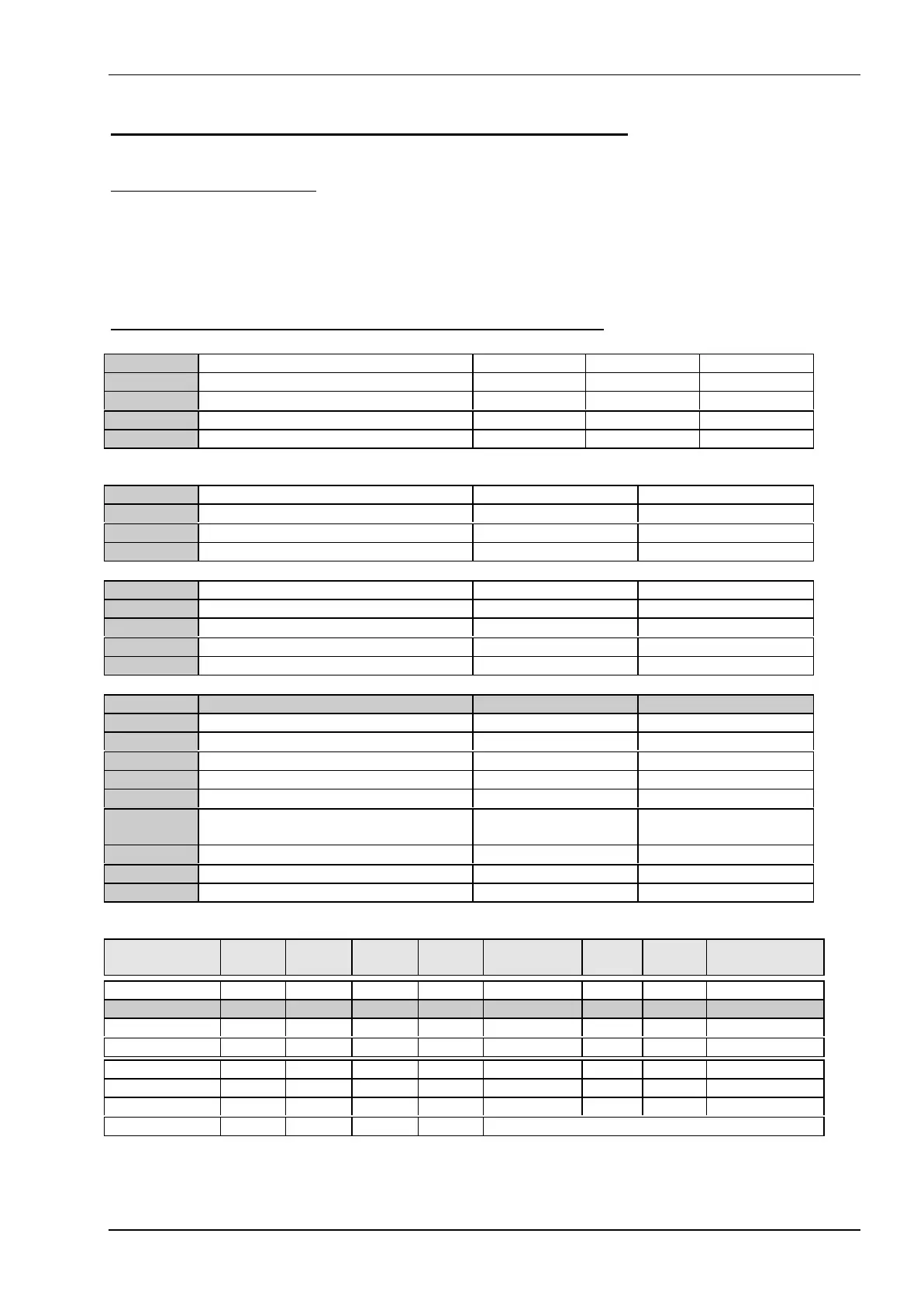
The figure shows the location of all the jumper blocks on the PCC-P5 board. The numbers shown in this fig-
ure are silk screened on the board so that the pins can easily be located. This chapter refers to the individual
pin for these jumpers. The default jumper settings are written in bold. Be careful when you change some
jumpers. Some jumpers are soldering jumpers so you need a miniature soldering station.
The Jumpers on the front side of the PCC-P5, (RM2.54mm jumpers)
J3, J4, J86 CPU Speed select J3 (BF0) J4 (BF1) J86 (BF2)
1.5 x CLK open open open
2 x CLK closed open open
2.5 x CLK closed closed open
3.0 x CLK open closed open
Please see also table below for different CPU’s and the correct BFx settings.
J7, J8 Clock selection J7 (CLKSEL1) J8 (CLKSEL0)
CLK = 50 MHz closed closed
CLK = 60 MHz open closed
CLK = 66 MHz closed open
J52, J53 Direct VGA-BIOS select J52 J53
BIOS 0 open open
BIOS 1 closed open
BIOS 2 open closed
BIOS 3 closed closed
Jumper Signals 1-2 = open 2-3 = closed
J26 BIOS address SA16 1-2 = recover mode 2-3 = normal mode
J27 RTC reset open = run closed = reset
J37 SCSI-2 termination open = disable closed = enabled
J51*** 2.9V CPU Support open = 2.9V closed = normal 3,3V
J59 PCI-BUS-Clock select (factory used) open = pull up =
25Mhz
closed = to PGOOD =
33Mhz
J75 Generic Digital Input (factory used) open = pull up closed = pulldown
J76 Generic Digital Input (factory used) open = pull up closed = pulldown
J81 to J85 Memory data interface (factory used) open = pull up closed = pulldown
Position: J41 J42 J43
Configuration IOS0 IOS1 IOS2 Base-Addr. IRQ Bus Interface
0 closed closed closed 340 5 8 AUI/COAX/WS
1 open closed closed 340 10 16 AUI/COAX/WS
2 closed open closed 320 11 16 AUI/COAX/--
3 open open closed 300 5 8 AUI/COAX
4 closed closed open 340 5 8 10BASE-T/WS
5 open closed open 340 10 16 10BASE-T/WS
6 closed open open 320 11 16 10BASE-T/--
7 open open open downloadable software configuration
*** MMX CPU: J51 off and (U3 assembled and R173=51kΩ for 2.9V)