DIGITAL-LOGIC AG PCCP5 Manual V2.3
130
13 BUILDING A SYSTEM
To build up a system based on your board, you should prepare the following equipments:
- A stable power supply of 5V (> 3 ampères), depending on the cpu, memory, etc.
- Assemble CPU with the proper clk- settings and cooling (fan) depending on board.
- If necessary, a 12V power supply for LCD or onboard sound.
- 8 ohm speaker for an executed beep code (if available on the board). One may use a capacity of 1µF
connected to VCC depending on the board.
- A micro- floppy disk drive (3,5") with a PC floppy cable (26 pin) or a standard FDD with appropriate cable
converter. You need at least one floppy to boot for the first time.
- A harddisk IDE 2,5" or 1,8" with the appropriate cable (44 pin and 2mm grid). Do not use a too long a
cable to avoid accessing problem as the IDE controller is may not able to drive the HDD.
- Connect a LCD or a monitor.
- Use an AT-compatible keyboard (5 PC) or (6 PC {PS/2} with an appropriate adapter).
- If desired, connect a mouse to it (COM or PS/2 if usable on the board).
- Connect a battery (Lithium 3V or NiMH 3.6V depending on the board) to store the data in the BIOS.
13.1 Starting up the System
Power-up the system and wait for the BIOS to show the BIOS activity on the screen. The BIOS diagnoses
the system and displays the size of the memory being tested. Note: you may can not bypass the memory
test depending on the BIOS producer.
CMOS-SETUP
If the CMOS configuration is incorrect, the BIOS tells you to enter the setup screen by pressing a key. Select
the correct options with the arrow keys and save them.
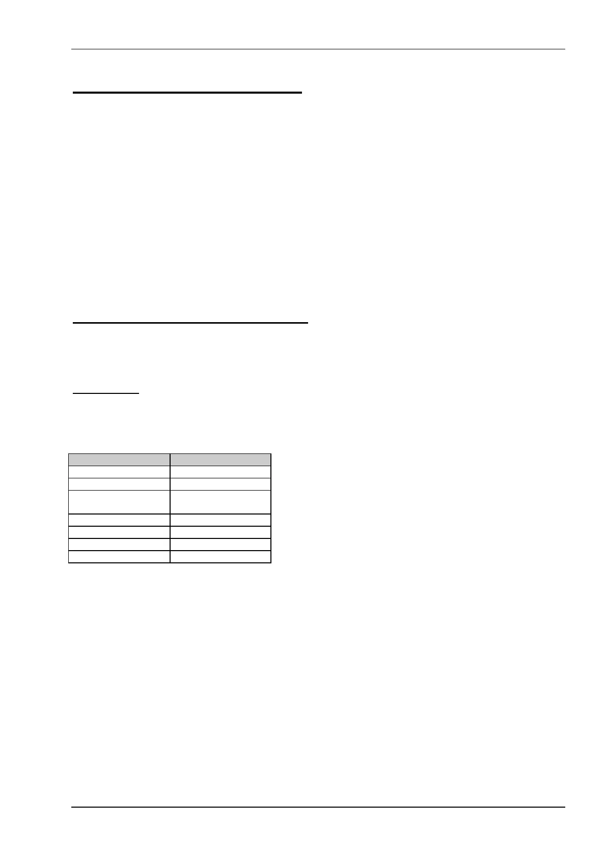
AMI
BIOS setup DEL
Change values PgUp /
PgDn
Jump ARROWS
Save F10
Back / exit ESC