DIGITAL-LOGIC AG PCCP5 Manual V2.3
25
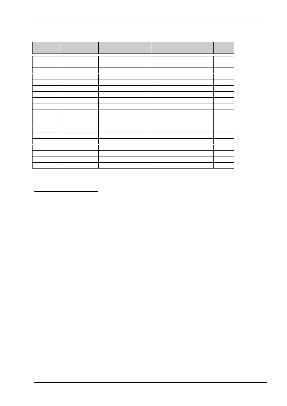
Floppy Disk Interface Connector
FD34:
Pin
FD26:
Pin Signal Name Function in/out
2 --- -RPM/-RWC Speed/Precomp (option) out
4 --- (Not used)
6 --- (Not used)
8 2 -IDX Index Pulse in
10 --- -MO1 Motor On 1 out
12 4 -DS2 Drive Select 2 out
14 --- -DS1 Drive Select 1 out
16 10 -M02 Motor On 2 out
18 12 -DIRC Direction Select out
20 14 -STEP Step out
22 16 -WD Write Data out
24 18 -WE Write Enable out
26 20 -TRKO Track 0 in
28 22 -WP Write Protect in
30 24 -RDD Read Data in
32 26 -HS Head Select out
34 6 -DCHG Disk Change in
1-33 25,23,21,19,17 GND Signal grounds
1,3,5 VCC +5 Volt
4.3.6 Speaker interface
One of the board's CPU device provides the logic for a PC compatible speaker port. The speaker logic signal
is buffered by a transistor amplifier, and provides approximately 0.1 watt of audio power to an external 8 ohm
speaker. The speaker must be connected to VCC (and not to Ground).
We propose to use a serial capacitor of 1µF with the speaker to eliminate any DC-current to protect the
speaker itself from overheating.