DIGITAL-LOGIC AG PCCP5 Manual V2.3
109
6 LED CRITERIONS:
LED Color Function
D2 Red Primary HDD
D5 Red LAN TX
D6 Red LAN RX
D7 Red LAN linked
D8 Red LAN busy
D9 Not defined
7 CABLE INTERFACE
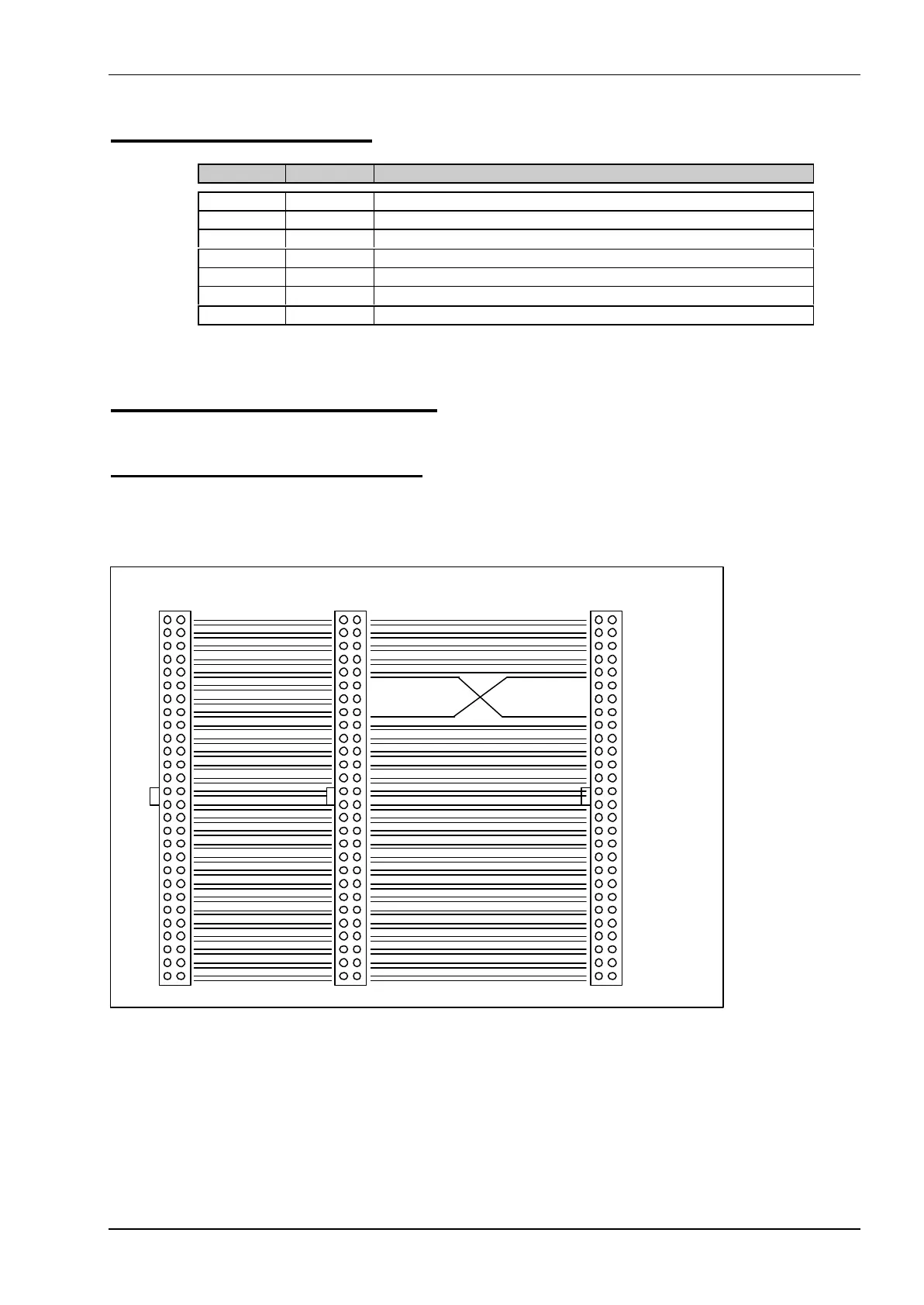
7.1 The Floppy Disk Cable
IDT Terminal for Dual Row 0.1" (2.54 mm grid) and 1.27 mm flat cable
1 2
33 34
1 2 1 2
MicroSpace
DRIVE B: DRIVE A:
10 10
16 16
Floppydisk Cable 34pin
max. cable length = 400mm
For drive A: the lines 10 to 16 are crossed (180 degrees).
All floppy drives must be selected as drive number 2, because the cable assigns the drive letter A: or B: to
the drives. The power must be connected separately. Refer to the technical manual of the floppy drives used.
The last drive must be terminated with 1 kohms. Do not use 150 ohms terminated floppy drives!