DIGITAL-LOGIC AG PCCP5 Manual V2.3
32
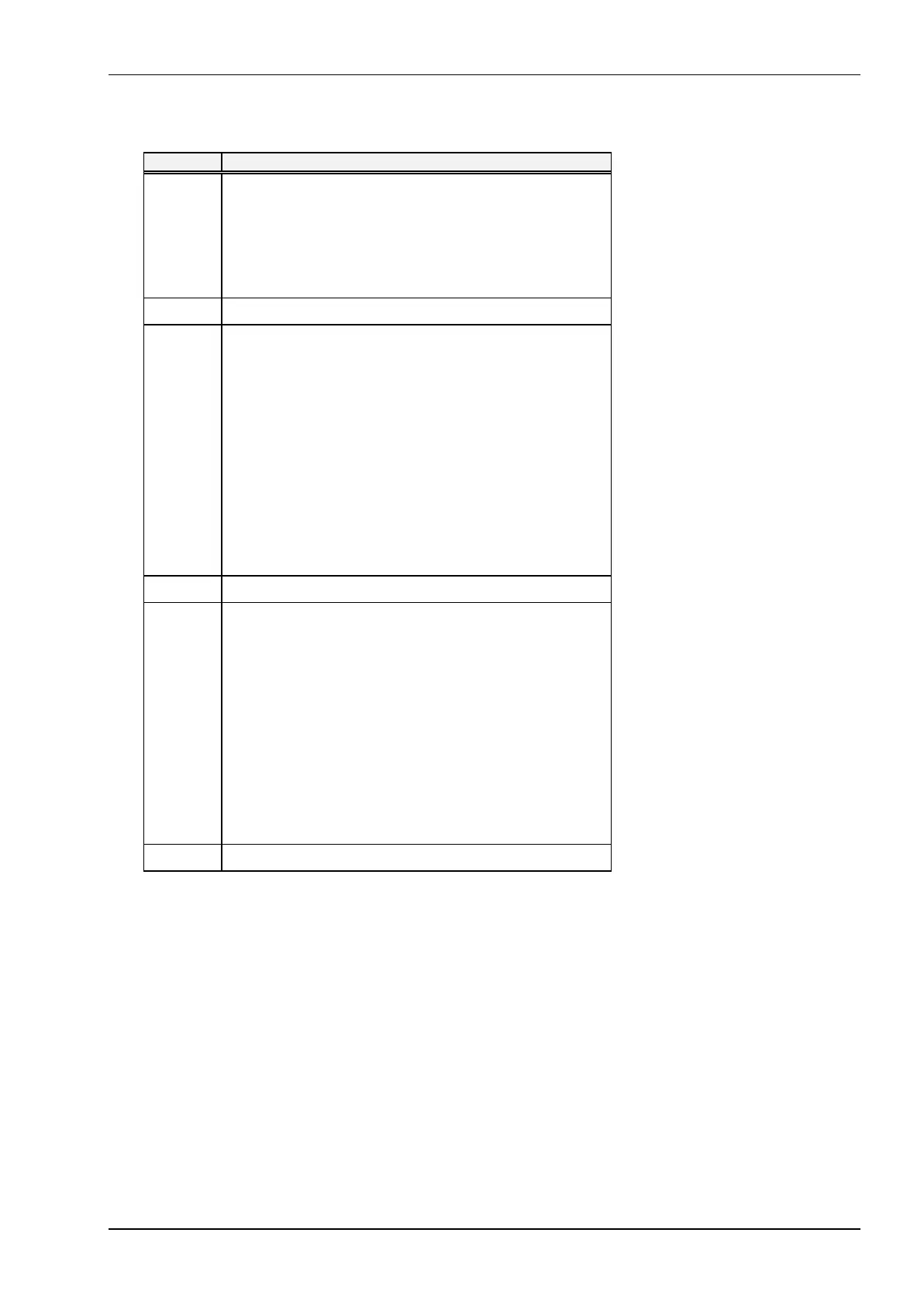
CMOS Map Continued...
Location Description
0Eh CMOS Location for Bad CMOS and Checksum Flags
bit 7 = Flag for CMOS Lost Power
0 = Power OK
1 = Lost Power
bit 6 = Flag for CMOS checksum bad
0 = Checksum is valid
1 = Checksum is bad
0Fh Shutdown Code
10h Diskette Drives
bits 7-4 = Diskette Drive A
0000 = Not installed
0001 = Drive A = 360 K
0010 = Drive A = 1.2 MB
0011 = Drive A = 720 K
0100 = Drive A = 1.44 MB
0101 = Drive A = 2.88 MB
bits 3-0 = Diskette Drive B
0000 = Not installed
0001 = Drive B = 360 K
0010 = Drive B = 1.2 MB
0011 = Drive B = 720 K
0100 = Drive B = 1.44 MB
0101 = Drive B = 2.88 MB
11h Reserved
12h Fixed (Hard) Drives
bits 7-4 = Hard Drive 0, AT Type
0000 = Not installed
0001-1110 Types 1 - 14
1111 = Extended drive types
16-44. See location 19h.
bits 3-0 = Hard Drive 1, AT Type
0000 = Not installed
0001-1110 Types 1 - 14
1111 = Extended drive types 16-44.
See
location 2Ah.
See the Fixed Drive Type Parameters Table in Chapter 2 for infor-
mation on drive types 16-44.
13h Reserved
Continued...