DIGITAL-LOGIC AG PCCP5 Manual V2.3
34
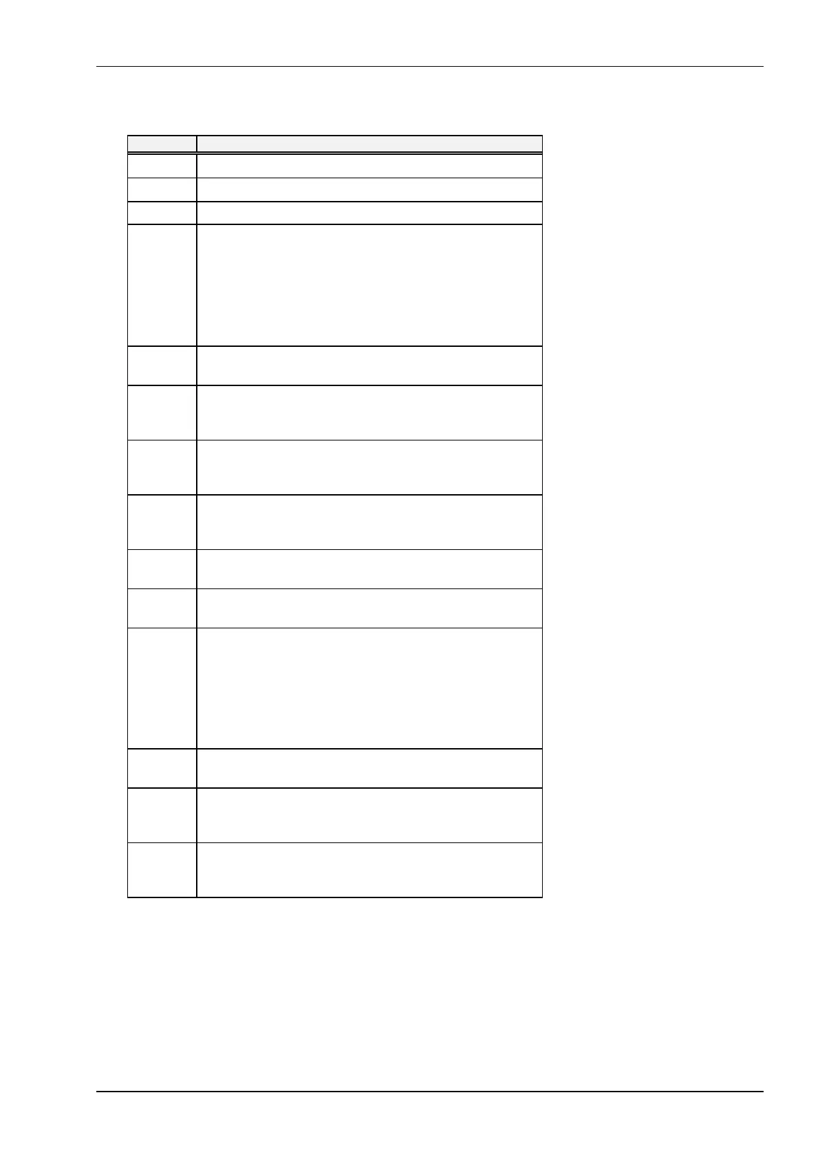
CMOS Map Continued...
Location Description
1Ch Reserved
1Dh EMS Memory Size Low Byte
1Eh EMS Memory Size High Byte
1Fh - 24h Custom Drive Table 0
These 6 bytes (48 bits) contain the following data:
Cylinders 10 bits range 0-1023
Landing Zone 10 bits range 0-1023
Write Precomp 10 bits range 0-1023
Heads 08 bits range 0-15
Sectors/Track 08 bits range 0-254
1Fh
Byte 0
bits 7-0 = Lower 8 Bits of Cylinders
20h
Byte 1
bits 7-2 = Lower 6 Bits of Landing Zone
bits 1-0 = Upper 2 Bits of Cylinders
21h
Byte 2
bits 7-4 = Lower 4 Bits of Write Precompensation
bits 3-0 = Upper 4 Bits of Landing Zone
22h
Byte 3
bits 7-6 = Reserved
bits 5-0 = Upper 6 Bits of Write Precompensation
23h
Byte 4
bits 7-0 = Number of Heads
24h
Byte 5
bits 7-0 = Sectors Per Track
25h - 2Ah Custom Drive Table 1
These 6 bytes (48 bits) contain the following data:
Cylinders 10 bits range 0-1023
Landing Zone 10 bits range 0-1023
Write Precomp 10 bits range 0-1023
Heads 08 bits range 0-15
Sectors/Track 08 bits range 0-254
25h
Byte 0
bits 7-0 = Lower 8 Bits of Cylinders
26h
Byte 1
bits 7-2 = Lower 6 Bits of Landing Zone
bits 1-0 = Upper 2 Bits of Cylinders
27h
Byte 2
bits 7-4 = Lower 4 Bits of Write Precompensation
bits 3-0 = Upper 4 Bits of Landing Zone
Continued...