DIGITAL-LOGIC AG PCCP5 Manual V2.3
46
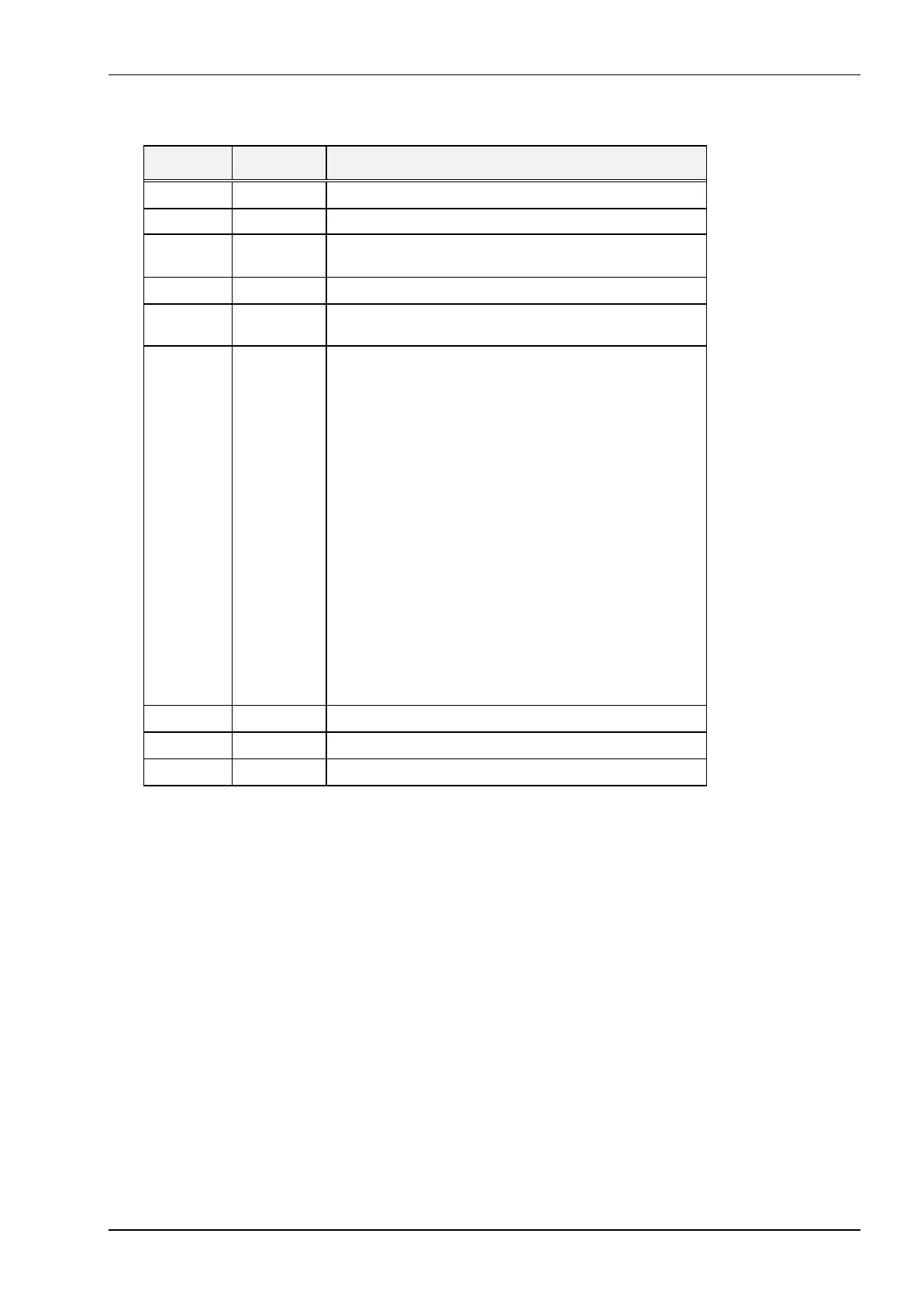
I/O Ad-
dress
Read/Write
Status
Description
0022h R / W Chipsset Register Address
0023h R / W Chipsset Register Data
0040h R / W Programmable Interrupt Time read/write counter 0, key-
board controller channel 0
0041h R / W Programmer Interrupt Timer channel 1
0042h R / W Programmable Interrupt Timer miscellaneous register
channel 2
0043h W Programmable Interrupt Timer mode port - control word
register for counters 0 and 2
bits 7-0 = Counter select
00 Counter 0 select
01 Counter 1 select
10 Counter 2 select
bits 5-4 = 00 Counter latch command
01 R / W counter, bits 0-7 only
10 R / W counter, bits 8-15 only
11 R / W counter, bits 0-7 first, then
bits 8-15
bits 3-1 = Select mode
000 Mode 0
001 Mode 1 programmable one shot
x10 Mode 2 rate generator
x11 Mode 3 square wave generator
100 Mode 4 software-triggered strobe
101 Mode 5 hardware-triggered strobe
bit 0 = 0 Binary counter is 16 bits
1 Binary counter decimal (BCD) counter
0048h R / W Programmable interrupt timer
0060h R Keyboard controller data port or keyboard input buffer
0060h W Keyboard or keyboard controller data output buffer
Continued...