DIGITAL-LOGIC AG PCCP5 Manual V2.3
52
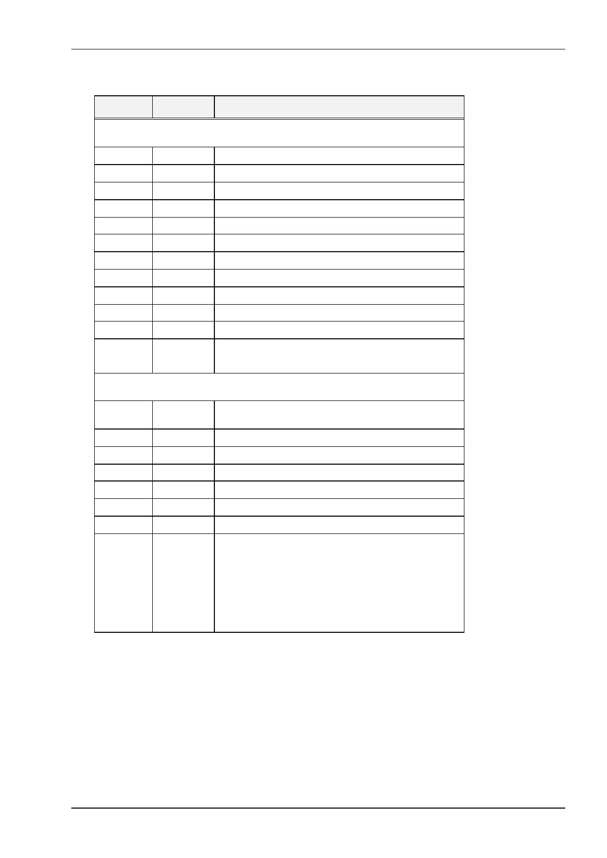
I/O Ad-
dress
Read/Write
Status
Description
I/O addresses 02F8h - 02FFh are reserved for use with serial port 2. See the bit defini-
tions for I/O addresses 03F8h - 03FFh.
02F8h W Transmitter holding register for serial port 2
02F8h R Receive buffer register for serial port 2
02F8h R / W Baud rate divisor (low byte) when DLAB = 1
02F9h R / W Baud rate divisor ( high byte) when DLAB = 1
02F9h R / W Interrupt enable register when DLAB = 0
02FAh R Interrupt identification register for serial port 2
02FBh R / W Line control register for serial port 2
02FCh R / W Modem control register for serial port 2
02FDh R Line status register for serial port 2
02FEh R Modem status register for serial port 2
02FFh R / W Scratch register for serial port 2 (used for diagnostics)
0300h –
031Fh
R / W LAN controller if installed
I/O addresses 0372h - 0377h are reserved for use with a secondary diskette controller.
See the bit definitions for 03F2h - 03F7h.
0372h W Digital output register for secondary diskette drive control-
ler
0374h R Status register for secondary diskette drive controller
0375h R / W Data register for secondary diskette drive controller
0376h R / W Control register for secondary diskette drive controller
0377h R Digital input register for secondary diskette drive controller
0377h W Select register for secondary diskette data transfer rate
0378h R / W Data port for parallel port 1
0379h R Status port for parallel port 1
bit 7 = 0 Busy
bit 6 = 0 Acknowledge
bit 5 = 1 Out of paper
bit 4 = 1 Printer is selected
bit 3 = 0 Error
bit 2 = 0 IRQ has occurred
bit 1-0 = Reserved
Continued...