DIGITAL-LOGIC AG PCCP5 Manual V2.3
88
J93 COM2 RS422/485 (4wire), new since V2.2
Pin Signal
Pin 1 TX+
Pin 2 TX-
Pin 3 RX+
Pin 4 RX-
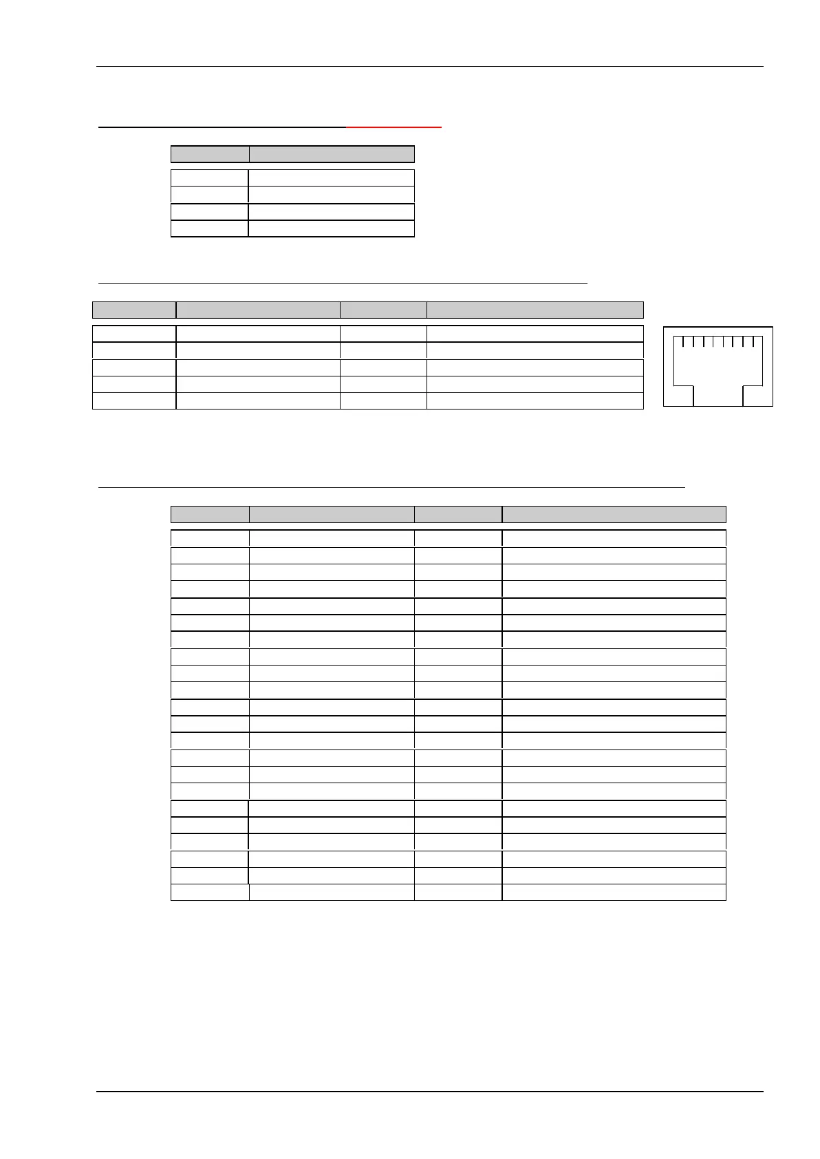
J64 Ethernet Twisted Pair interface 10/100Mhz, (assembling option)
Pin J64 * Signal RJ-45 Pin Signal
Pin 1 = TX+ Pin 1 = TX+
Pin 2 = TX- Pin 2 = TX-
Pin 3 = RX+ Pin 3 = RX+
Pin 4 = RX- Pin 6 = RX-
Pin 4,5,7,8 pull down with 75ohms
* This signals are ready to connect directly to a RJ-45 connector.
J23 Optionally assembled IDE interface connector 44 pins RM2.00mm on rear side
Pin Signal Pin Signal
Pin 1 = Reset (active low) Pin 2 = GND
Pin 3 = D7 Pin 4 = D8
Pin 5 = D6 Pin 6 = D9
Pin 7 = D5 Pin 8 = D10
Pin 9 = D4 Pin 10 = D11
Pin 11 = D3 Pin 12 = D12
Pin 13 = D2 Pin 14 = D13
Pin 15 = D1 Pin 16 = D14
Pin 17 = D0 Pin 18 = D15
Pin 19 = GND Pin 20 = NC (keypin)
Pin 21 = DRQ0 Pin 22 = GND
Pin 23 = IOW (active low) Pin 24 = GND
Pin 25 = IOR (active low) Pin 26 = GND
Pin 27 = IORD4 Pin 28 = VCC pullup
Pin 29 = DACK0 Pin 30 = GND
Pin 31 = IRQ14 Pin 32 = IOCS16 (active low)
Pin 33 = ADR1 Pin 34 = NC
Pin 35 = ADR0 Pin 36 = ADR2
Pin 37 = CS0 (active low) Pin 38 = CS1 (active low)
Pin 39 = LED (active low) Pin 40 = GND
Pin 41 = VCC Logic Pin 42 = VCC Motor
Pin 43 = GND Pin 44 = NC
1 2 3 4 5 6 7 8