159
DCS-3950 series Ethernet switch manual
VLAN200
VLAN100
VLAN2
VLAN200
VLAN100
VLAN2
IBM PC
IBM PC
Workstation Workstation
Desktop PC
Desktop PC
IBM
PC
IBM PC
Workstation Workstation
Desktop PC
Desktop PC
Switch A
Switch B
Trunk Link
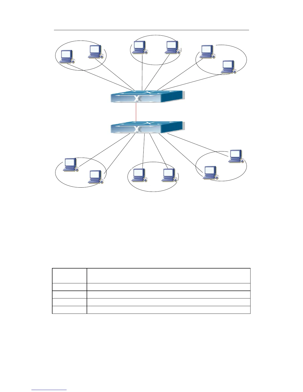
Fig 9-2 Typical VLAN Application Topology
The existing LAN is required to be partitioned to 3 VLANs due to security and
application requirements. The three VLANs are VLAN2, VLAN100 and VLAN200. Those
three VLANs are cross two different location A and B. One switch is placed in each site,
and cross-location requirement can be met if VLAN traffic can be transferred between the
two switches.
Configuration
Item
Configuration description
VLAN2 Site A and site B switch port 2 -8.
VLAN100 Site A and site B switch port 9 -15.
VLAN200 Site A and site B switch port 16 -22.
Trunk port Site A and site B switch port 23.
Connect the Trunk ports of both switches for a Trunk link to convey the cross-switch
VLAN traffic; connect all network devices to the other ports of corresponding VLANs.
In this example, port 1 and port 24 is spared and can be used for management port or
for other purposes.
 Loading...