202
DCS-3950 series Ethernet switch manual
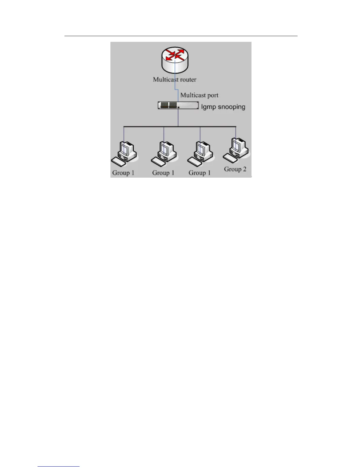
Fig 11-1 Enabling IGMP Snooping function
Example: As shown in the above figure, a VLAN 100 is configured in the switch and
includes ports 1, 2, 6, 10 and 12. Four hosts are connected to port 2, 6, 10, 12 respectively
and the multicast router is connected to port 1. As IGMP Snooping is disabled by default
either in the switch or in the VLANs, If IGMP Snooping should be enabled in VLAN 100,
the IGMP Snooping should be first enabled for the switch in Global Mode and in VLAN
100 and set port 1 of VLAN 100 to be the M-Router port.
The configuration steps are listed below:
switch#config
switch (config)#ip igmp snooping
switch (config)#ip igmp snooping vlan 100
switch (config)#ip igmp snooping vlan 100 mrouter-port interface ethernet 0/0/1
Multicast Configuation:
Assuming that there are two multicast servers: Multicast Server 1and Multicase Server 2.
Multicast Server 1 provides program1 and program 2 while the Multicast Server 2
provides program3. And they use group addresses Group1,Group2 and Group 3
respectively. There are four hosts running multicast application software simultaneously,
the two of which connected to port 2 and 6 order program 1, the one connected to port 10
orders program2 and the other one connected to port 12 orders program 3
IGMP Snooping listening result:
The multicast table built by IGMP Snooping in VLAN 100 indicates ports 1, 2, 6, 10 in
Group1 and ports 1, 12 in Group3.
All the four hosts can receive the program of their choice: ports 2, 6, 10 will not receive the
traffic of program 2,3and port 12 will not receive the traffic of program 1,2.
 Loading...