ASE 150 Operator’s Manual
102 Doc. 065207-02 9/08
5.10 Replacing the Main Power Fuses
1. Turn off the ASE 150 power switch and disconnect the power cord from both
its source and from the ASE 150 rear panel.
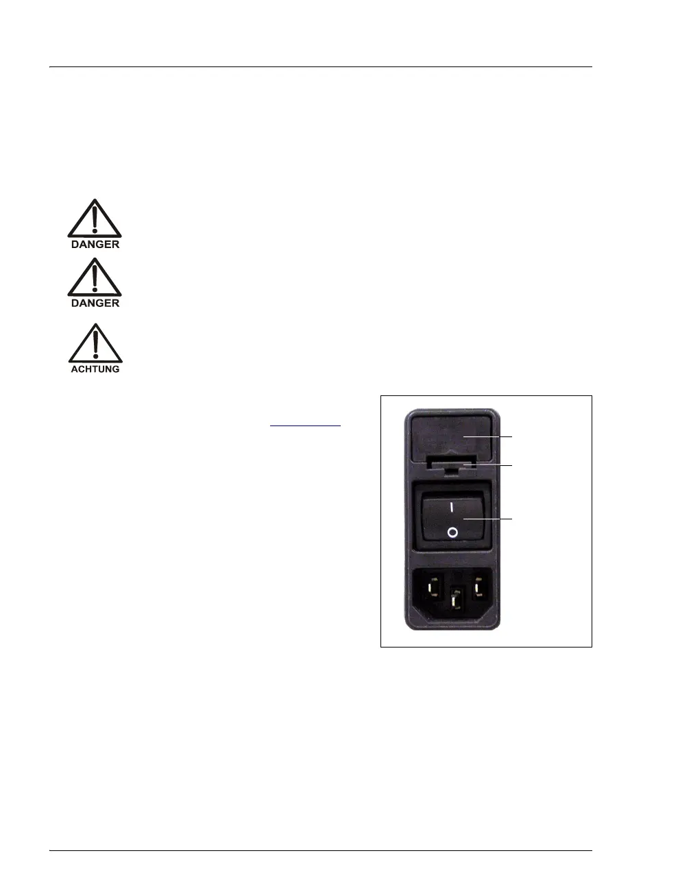
2. The fuse drawer is located above the
main power switch (see Figure 5-27
). A
small tab locks the fuse drawer in place.
Using a small screwdriver, press the tab
in and then up to release the fuse drawer.
3. Pull the fuse drawer out of the rear panel
and remove the old fuses. Dionex
recommends always replacing both
fuses.
4. Insert two new 10 amp IEC127 fast-blow
fuses (P/N 954746) into the springs in
the fuse drawer. Press gently to fully
insert the fuses into the drawer.
Figure 5-27. Fuse Drawer
5. Insert the fuse drawer into the rear panel and press until the drawer snaps into
place.
6. Reconnect the power cord and turn on the power switch.
HIGH VOLTAGE—Disconnect the main power cord from its source, as
well as from the rear panel of the ASE 150.
HAUTE TENSION—Débranchez le cordon d'alimentation principal de
sa source et du panneau arrière du ASE 150.
HOCHSPANNUNG—Ziehen Sie das Netzkabel aus der Steckdose und
der Netzbuchse auf der Rückseite des ASE 150.
Fuse
Drawer
Main Power
Switch
Tab