ASE 150 Operator’s Manual
84 Doc. 065207-02 9/08
7. Turn on the ASE 150 main power switch.
8. Reset the
PUMP STROKE counter on the EXTRACTION COUNTERS
screen (see Section C.2.5
).
5.7 Replacing the Pressure Relief Valve
1. Follow the instructions in Section 5.4 to disconnect the gas source and
remove the right-side panel.
2. The pressure relief valve is installed in the upper left corner of the component
panel (see Figure 5-18
, ). Disconnect the yellow gas tubing ( ) from the
elbow press fitting on the valve.
To disconnect a press fitting, use your fingers (or a small open-end wrench) to
press the ring on the fitting in, while at the same time pulling the tubing out.
3. Use a 1/4-inch open-end wrench to disconnect the stainless steel line ( )
from the right side of the valve. (This tubing connects to the pump
transducer.)
4. Use the wrench to disconnect the Hastelloy® line ( ) from the left side of
the valve. (This tubing connects to the upper AutoSeal tip.)
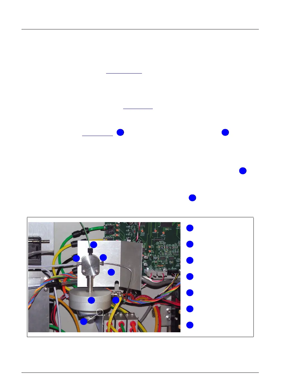
Figure 5-18. Connections to the Pressure Relief Valve
11 22
3
3
44
Pressure Relief Valve
Hastelloy Line
Green PEEK Waste Line
Stainless Steel Line
Yellow Gas Tubing
Allen Hex Screw
2
4
5
3
1
6
1
2
3
4
5
6
7
7
Splash Guard