2 • Description
Doc. 065207-02 9/08 15
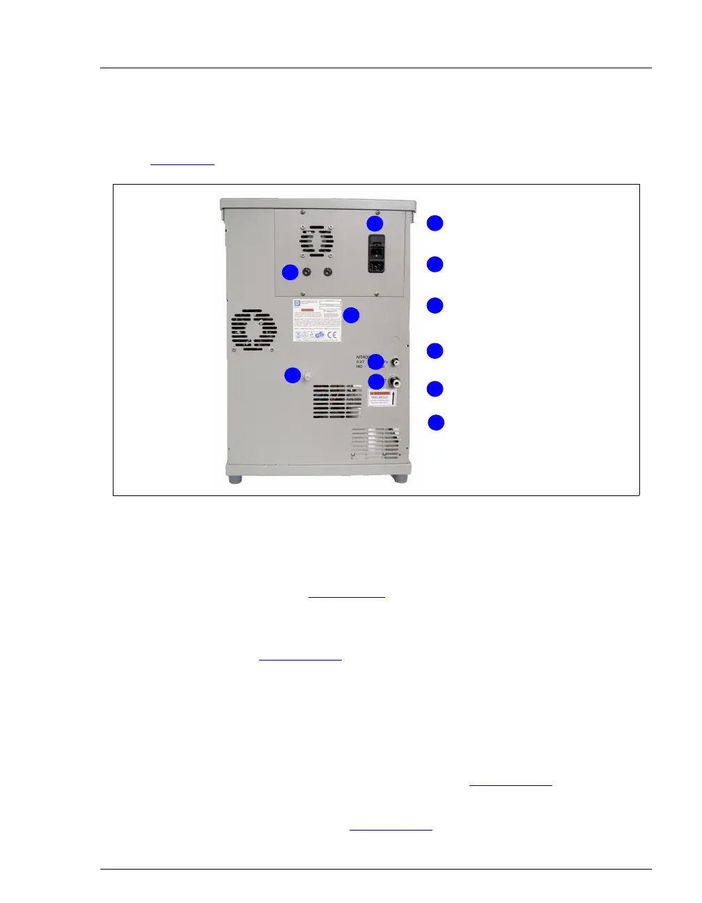
2.2 Rear Panel
Figure 2-3 illustrates the rear panel of the ASE 150.
• The POWER switch provides on/off control of the main power for the system.
The power receptacle also includes the fuse holder. For instructions on how to
replace the fuses, see Section 5.10
.
• The oven voltage switches must be set to match the voltage from the power
source at the ASE 150 installation site. For instructions on how to set the
switches, see Section B.2.3
.
• The model data label lists fuse and power information, as well as the ASE 150
serial number. You will be asked to provide the serial number when ordering
replacement parts for the system.
• The NITROGEN connector is connected to a nitrogen supply regulated to
between 0.97 and 1.38 MPa (140 and 200 psi); 1.03 MPa (150 psi) is
recommended. For installation instructions, see Section B.2.1
.
• The VENT connector provides a connection for the vent outlet line. For
installation instructions, see Section B.2.1
.
Figure 2-3. ASE 150 Rear Panel
1
Power
Nitrogen Gas
Inlet
2
Vent Outlet
4
5
3
1
2
Model Data
Label
Oven Voltage
Switches
4
5
3
6
6
Drain