ASE 150 Operator’s Manual
76 Doc. 065207-02 9/08
5. Disconnect the gray cable from the pump PC board ( ).
6. Use a 3-mm hex screwdriver (P/N 060154) to remove the screws in
the left and right end plates ( ) on the pump. These screws secure
the pump to the component panel.
5.5.3 Removing the Check Valves and Cartridges
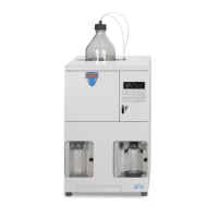
1. Use a 1/2-inch open-end wrench to loosen the inlet check valve
housing. Remove the housing and then remove the check valve
cartridge from the housing (see Figure 5-8
).
2. Turn the pump over, so that the outlet check valve is facing down.
3. Use a 1/2-inch open-end wrench to loosen the outlet check valve
housing. Remove the housing and then remove the check valve
cartridge from the housing.
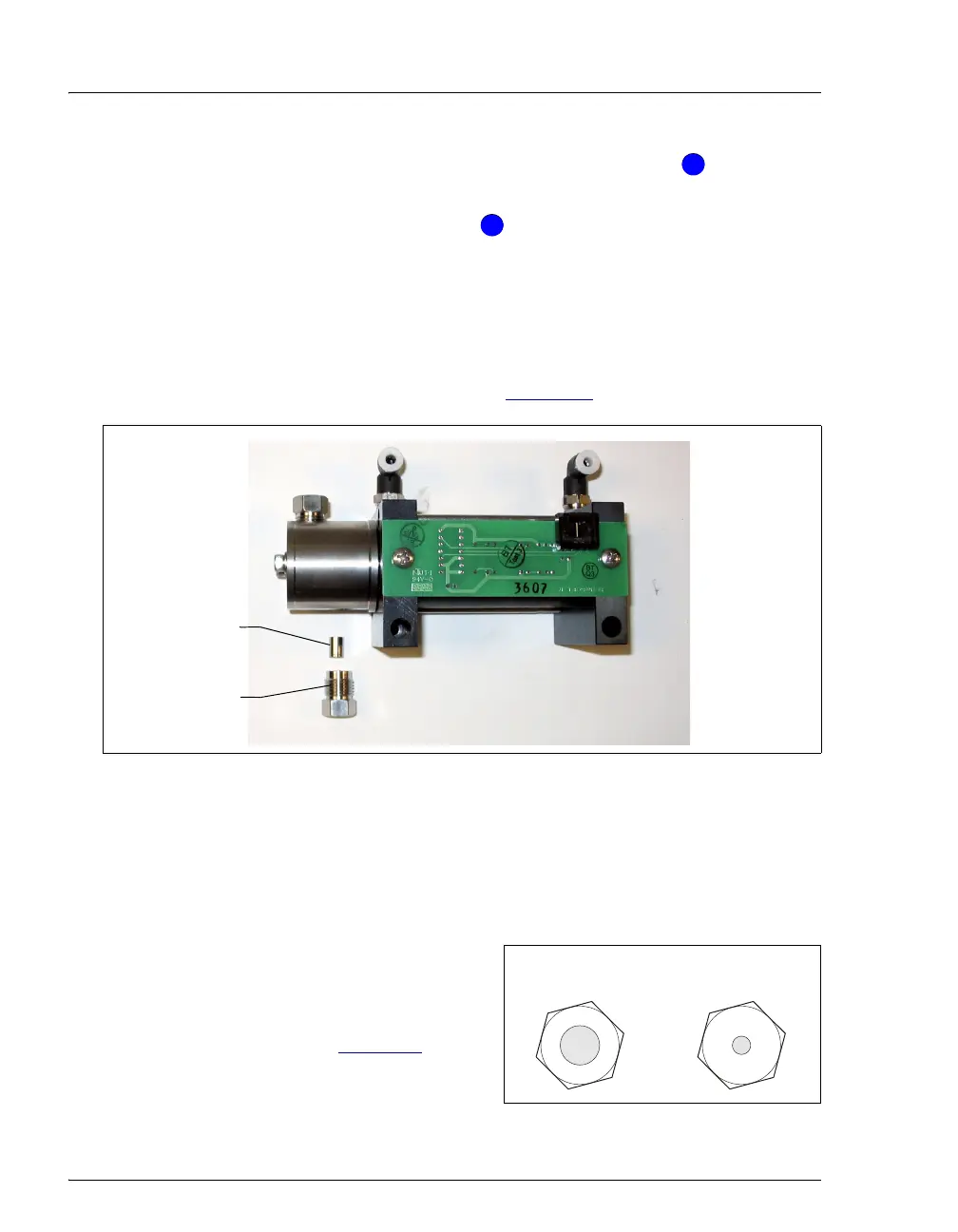
NOTE The housing for the inlet check
valve assembly has a 1/4-28
port. The housing for the outlet
check valve assembly has a 10-
32 port (see Figure 5-9
).
Figure 5-9. Check Valve Housings
Figure 5-8. Disassembled ASE 150 Pump Inlet Check Valve
4
4
5
5
Inlet Check
Valve Housing
Inlet Check
Valve Cartridge
Inlet Check Valve:
1/4-28 Port
Outlet Check Valve
10-32 Port