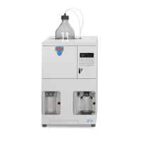
ASE 150 Operator’s Manual
66 Doc. 065207-02 9/08
transducer fittings, pressure relief valve fittings, static valve fittings, and
solvent line fittings. Use a 1/4-inch open-end wrench (P/N 049452) to tighten
any leaking fittings. Do not overtighten!
If tightening does not stop a leak, the tubing and fitting assembly must be
replaced. Contact Dionex for assistance.
If the pump head is leaking, replace the pump seals (see Section 5.6
).
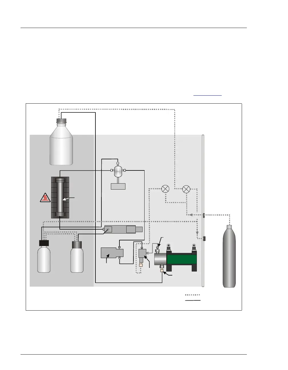
Figure 4-1. ASE 150 Plumbing Diagram
Pressure
Relief
Valve
Waste
Bottle
Collection
Vessel
Sample
Cell
Oven
Solvent
Bottle
Purge
Valve
Prime
Valve
Rear Panel
Nitrogen
In
Vent
Pump
Outlet
Pump
Pressure
Transducer
Check
Valve
Pump
Inlet
Static Valve
Front Components Right-Side Components
= Gas Lines
= Solvent Line