ASE 150 Operator’s Manual
74 Doc. 065207-02 9/08
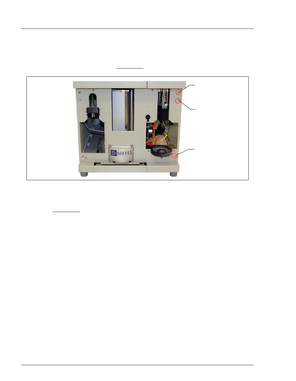
8. Using a #2 Phillips screwdriver, remove the two screws on the right side of
the inner front panel. One screw is at the top right corner; the other is at the
bottom right corner (see Figure 5-6
).
9. Insert a screwdriver into the opening located beneath the top screw hole (see
Figure 5-6
). Push the screwdriver in until the right-side panel slides back
about 1/2 inch. To prevent scratches or other damage to the panel, do not
let the panel fall onto the workbench.
10. Remove the right-side panel from the system and set it aside.
Reinstalling the Right-Side Panel
1. Hold the panel against the right side of the system. Engage the small tabs on
the top and bottom of the panel with the slots in the chassis. Pull the panel
forward until it locks into place.
2. Replace the two Phillips screws on the inner front panel.
3. Slide the drip tray out about halfway.
4. Carefully align the lower trim panel with the edges of the instrument, and then
gently push the panel into place.
5. Reinstall the waste bottle and collection vessel.
6. Reconnect the gas source and turn on the gas supply.
7. Turn on the ASE 150 main power switch.
Figure 5-6. Inner Front Panel
Remove this
screw
Remove this
screw
Opening for
screwdriver