Danish Interpretation Systems User Manual
9.5 Connection Details
Mains
Blue Neutral
Brown Live
Green/YellowEarth(Ground)
Chain(DCSLAN)
TheDDS5900systemusesCat5e,Cat6orCat7F/UTP
J45connectors.orU/FTPcableswithscreenedR
EIA568‐Bwiringshallbeused.
Important: The names of Cat5/6/7 cable type have
changed.
Oldname Newname
FTP F/UTP
STP U/FTP
UTP U/UTP
Important: Use only F/UTP or U/FTP (screened)
cablesandscreenedRJ45connectorsandnotU/UTP
cable,whichareunscreened.
HowtowireaCat5e(EIA568‐B)cabletoaRJ45con.:
Pin Function Connector#1 Connector#2
1 Ingoing+ ORG/WHT ORG/WHT
2 Ingoing ORG ORG
3 +48V GRN/WHT GRN/WHT
4 0V BLU BLU
5 0V BLU/WHT BLU/WHT
6 +48V GRN GRN
7 Outgoing BRN/WHT BRN/WHT
8 Outgoing+ BRN BRN
Note: If other color codes are used then the four
pairsar onnectedec asfollows:
Pair2: Pin1&2
Pair3: Pin3&6
Pair1: Pin4&5
Pair4: Pin7&8
Thephaseofthepairsmustbecorrectandthewiring
spec. as stated in Cat5e (EIA 568‐B) have to be
followed.
Note: Cat6 and Cat7 cables can normally only be
terminatedinsockets(female)andnotin abl plugs.c e
Cat6 and Cat7 can thus only be used for feeding
cablesterminatinginwalloutletsorpatchpanels.
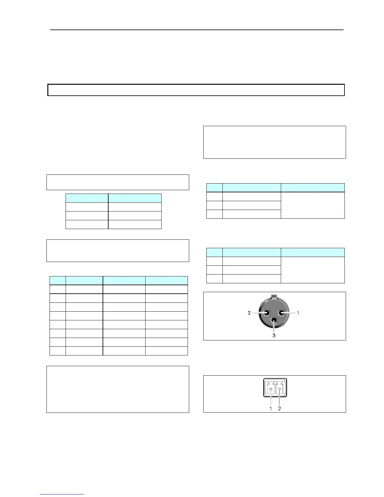
AnalogAudioOut
XLR3male
Pin Signal Cabletype
1 Earth
2 Signal+
3 Signal–
2x0.25mm2shielded.
AnalogAudio
XLR3female
In
Pin Signal Cabletype
1 Earth
2 Signal+
3 Signal–
2x0.25mm2shielded.
Emergencyswitch
Terminalblock
Connecttheemergencyswitchtopin1and2.
User Manual DDS 5900
43