16
Establish Communication with SMARTBOX
Connect SMARTBOX to Ethernet
1. Connect an Ethernet cable between the port labeled Data 1 (located to the right of the DISH logo on the front
of SMARTBOX) and an Ethernet port on a router or computer (See Figure 6.).
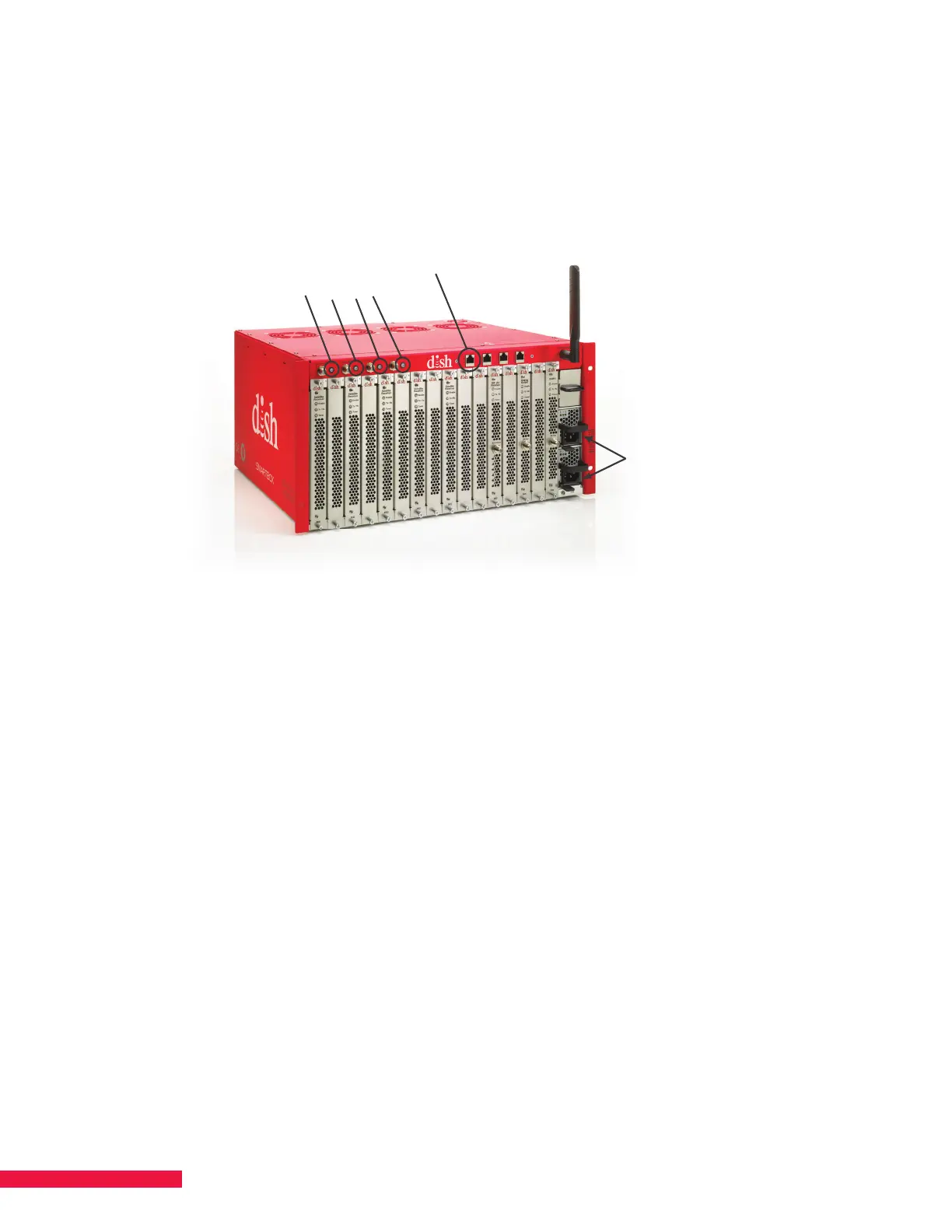
Figure 6. Ethernet Port – Data 1
4 LED Indicators
Data 1 (Ethernet)
Power
Supplies
2. Plug the SMARTBOX power supply into an uninterruptible power supply (UPS) providing AC power.
The system powers on and self-boots.
• Four LED indicators located next to the satellite ports on the front of chassis blink during boot.
• LEDs turn solid when boot-up is complete. Please see Chapter 20 LED Information for more detailed
explanation of the dierent LED colors. System boot-up may take up to 5 minutes.
Connect Cables to Connectors and Install Cellular Antenna
1. Connect a cable from an external terrestrial antenna to the “Antenna In” connector on the front of the
ATSC blade (if installed). If more than one ATSC blade is installed, use a splitter to connect the blades
to the same antenna.
2. Connect the QAM blade output port to the cable plant. If SMARTBOX contains multiple output blades
(e.g., QAM and NTSC), use an external combiner to combine their signals on a single coax cable.
3. Screw the cellular antenna into the SMA connector located on the upper right corner of the front
of SMARTBOX. The cellular antenna is provided with the SMARTBOX chassis; however, depending on your
install, you may need to use a third-party antenna extender to achieve connectivity.