6400-065-C-1-09
21
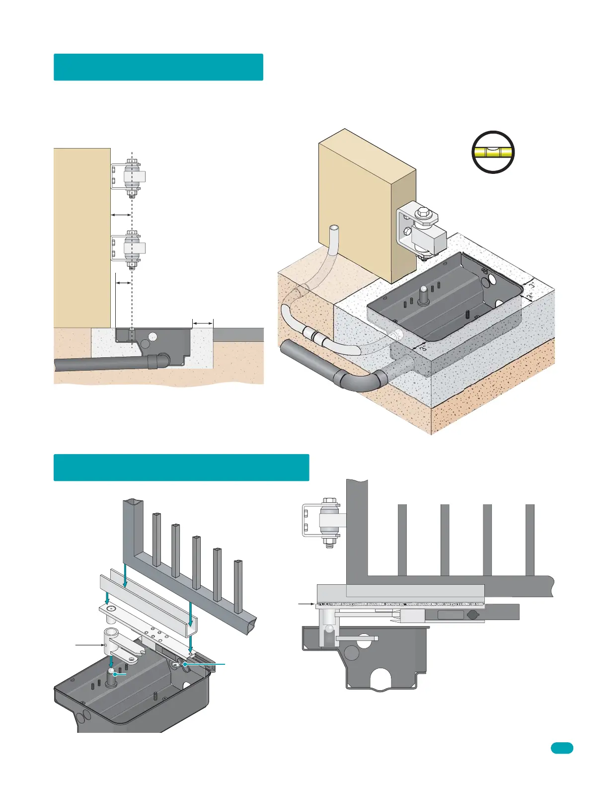
The gate weight is supported by the gate hinges and NOT on the foundation box. This is preferred for heavy gates.
The foundation box MUST have a drain pipe installed with the correct slope for proper drainage. Improper drainage of the
foundation box will result in stagnant water that will lead to operator failure eventually.
6400 Two Hinge Setup
Ball Bearing Hinge
P/N 1200-039
2 3/4” Hinge pivot point.
Wall
or
Post
2 5/8” operator pivot point.
Sample Hinges
3” around
foundation box.
Driveway
1 1/2” pipe slop
e
d to drain.
Foundation
Box
The depth of the concrete is determined by
specific installation requirements, soil conditions
and local building codes.
Important: Hinge pivot
points MUST align with
foundation box pivot point.
Good
Drainage
Two Hinge Gate Connection
Apply Grease
Grease
Filler
Hole
Foundation box MUST be level
and flush with driveway surface.
Foundation Box
3
”
3”
3”
Slope 1 1/2” drainage
pipe away
from foundation box to nearest
drain (Not sup
pl
ied
)
.
Fabricated U-Channe
l (Not Supplied)
M
anual
R
eleas
e
Weld both
sides of
U-channel
to manual
release.
Gate is supported by hinges and does
not have to rest on foundation box.
Do not weld gate to U-channel.
After the foundation box has been mounted
and the gate has been connected to it, proceed
to page 22 to install components in the box.
Protect the manual release
from welding sparks during
welding.
Run 3/4” conduit
with sweeps from
foundation box to
where control box
will be mounted.
Manual
Release
Manual
Release
Unlock and pull release
handle to manually
operate the gate.
Important: Remove all parts
from inside of foundation box
before mounting into concrete.