6400-065-C-1-09
27
Key Switch
(Dry contact)
Keypad
(Dry contact)
12345
6
7
89
10 11 12
13
14 15
16 17 18 19
20
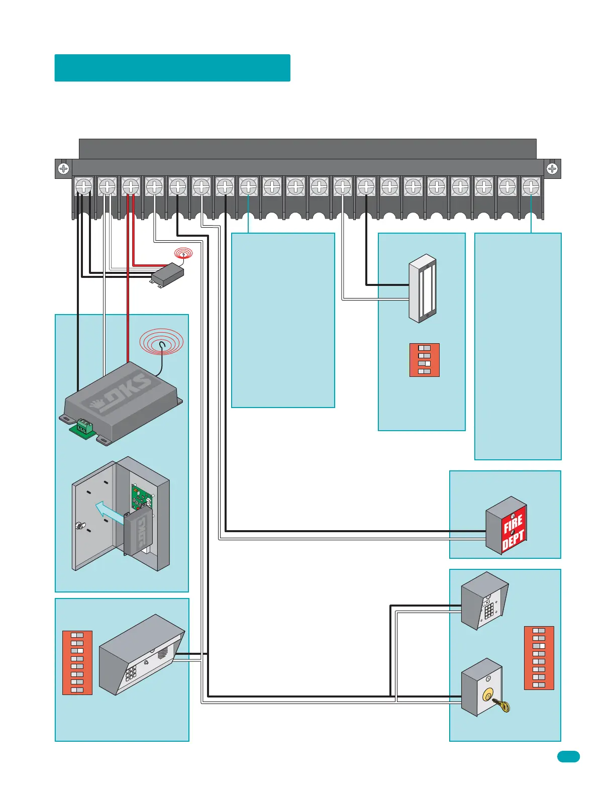
3.4 Main Terminal Wiring
1
ON
2 3 4
SW 2
Switch 3 ON
Controls must be far enough from the gate so that the user is prevented from coming in contact with the gate while operating
the controls. Outdoor or easily accessible controls should have a security feature to prevent unauthorized use. When installing
electrical equipment make certain all wiring complies with local code requirements. Do not power any control devices from the
circuit board other than low voltage devices.
Connect optional
control devices to
the main terminal
strip. Use 18 AWG
wire for all low
voltage wiring,
maximum distance
3000 feet. Use a
low voltage surge
suppressor,
(DoorKing P/N
1878-010) if low
voltage wire runs
exceed 1000 feet.
All inputs to the
terminal strip must
be NORMALLY
OPEN.
1. Com
Relay Com
Relay N.O.
24 Volt Power Com
24 Volt Power
Com
Com
Com
N.O.
N.O.
N.O.
Com
N.C.
3. 24 Volt
2. Relay
Magnetic Lock
3-Wire Receiver
4-Wire
Receiver
Mount inside of
control box door.
Reversing input on
Terminal 8 only
functions while the
gate is at the full open
position or during the
closing cycle. It should
not be used as an
input for a secondary
entrapment protection
device during the
opening gate cycle.
Refer to Section 3.2
Secondary Entrapment
Protection Wiring.
Knox Box
(Dry contact)
1
ON
2 3 4 5 6 7 8
SW 1
Switch 3 ON
1
ON
2 3 4 5 6 7 8
SW 1
Switch 3 ON
Telephone Entry
Note: Telephone entry device
must use a separate power
source.
Note: Circuit board
provides 24 VDC to
power maglock.
Com
N.O.