6400-065-C-1-09
32
4.2 DIP-Switch Settings Continued
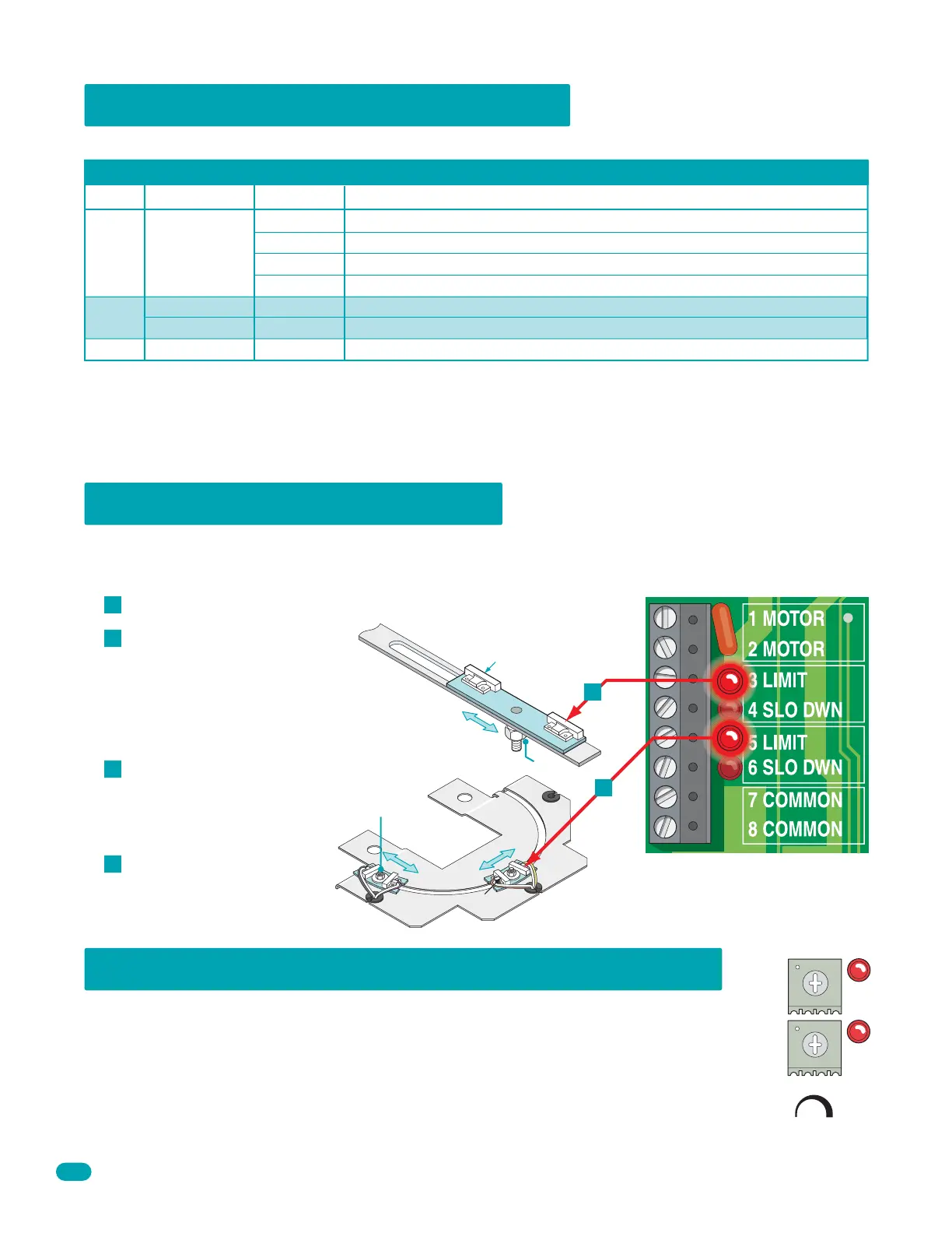
4.3 Limit Sensor Adjustments
Switch Function Setting Description
SW 2 (Bottom 4 Switches)
Whenever any programming or switch setting on the control board is changed, press the reset switch for new settings to take effect.
Switch 1 and 2 These work in conjunction with each other and determine when the relay on the board will be activated. This
relay can be used as a switch for various functions such as illuminating a warning light when the gate is moving, or turning on a
green light when the gate is full open. This relay is not available for these uses if it is being used for the shadow loop function.
Switch 3 Used for a maglock or a DK deadbolt lock.
Switch 4 Spare switch. Leave in OFF position.
1-OFF
1-OFF
1-ON
1-ON
2-OFF
2-ON
2-OFF
2-ON
Relay activates when gate is fully open.
Relay activates when gate is not closed.
Relay activates when gate is opening and open.
Relay activates when gate is opening and closing.
Spare Leave in the OFF position.
OFF
Relay
Operation
1 and 2
3
4
1 second delay to disengage maglock.
4-5 seconds delay to retract dead-bolt.
ON
OFF
Maglock
DK Deadbolt Lock
The limit sensors must be adjusted to precisely set the full open and full closed position of the gate. This feature is especially
useful in applications where the gate opens partially, such as on a curved driveway. Power to the circuit board must be ON
when adjusting the limit switches.
Slow Down
Limit Nut
Lim
it
Nut
Manually move the gate to the
desired open or closed position.
Loosen the limit nuts and slowly
slide the limit assembly until the
LIMIT LED on the circuit board
lights up.
Tighten the limit nuts, re-lock
operator with key and test the
gate stopping positions. Repeat
if necessary.
Re-install the cover. Adjust the
secondary operator limit
sensors if dual operators have
been installed.
Note: 3 and 5 limit LEDs can be
Open or Close limits according to
SW 1, switch 1 and 2 settings.
Manually release operator with key and remove cover with 3 or 4 screws.
A
B
C
D
B
6002 or 6003
Slow
Down
6400
B
4.4 Inherent Entrapment Sensing Adjustment
This vehicular gate operator is equipped with an inherent adjustable reversing sensor (Type A) that is used as the
primary entrapment sensing system according to the UL 325 standards. The gate will reverse direction upon
encountering an obstruction in either the opening or closing gate cycle. For the reverse system to function
correctly, the gate must be properly installed and work freely in both directions. A good set of roller bearing
hinges is essential for proper swing gate operation.
The ideal adjustment will allow the operator to move the gate through its entire travel cycle without reversing, but
will reverse upon contact with an obstruction with no more than 40 Lbs of force. This force can be measured with
a gate scale, DoorKing P/N 2600-225. Continued on next page.
Secondary
Primary
Min Max
Sensitivity