6400-065-C-1-09
22
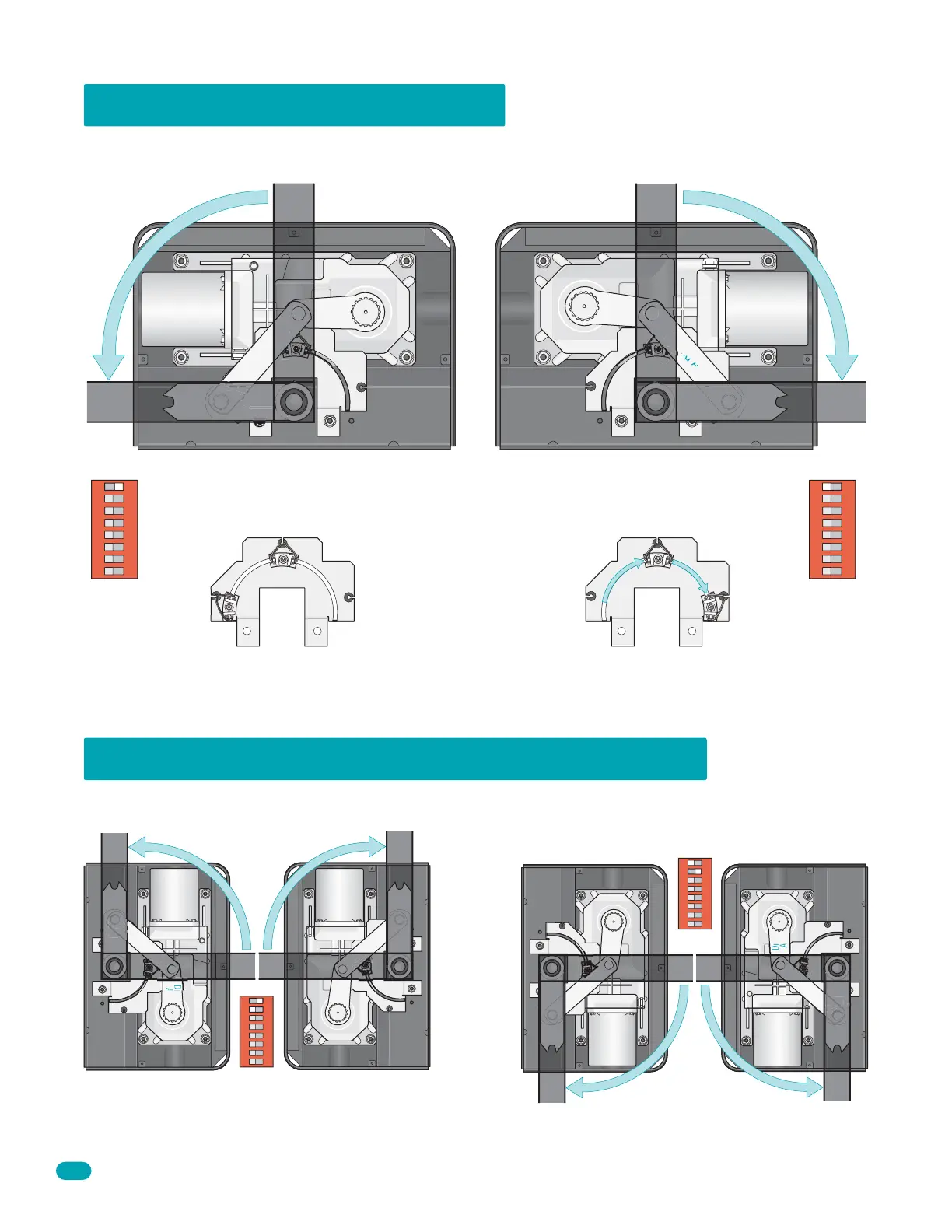
The drive motor orientation determines the opening direction of the gate. It can be unbolted and flipped 180° to allow the gate to
open in either direction. See setups below for your specific opening direction. Factory setup opens gate counter-clockwise.
The secondary operator motor wires must be reversed if dual operators are used (Blue wire to #1 and Brown wire to #2).
See page 24 for more information.
Arms shown in
open position.
Limit sensors are factory set in the
“Open counter-clockwise” position.
Drive motors face the same direction in a dual gate installation.
Limit sensors are positioned according to the opening direction of the gate (See limit plates shown above).
6400 Gate Opening Direction
6400 Dual Gates Opening in Either Direction
Drive
Arm
Drive
Motor
Linking Arm
Limit sensors must be slid 90° clockwise on limit plate
to be in the correct “Open clockwise” position.
Note: Final limit adjustments will be made after AC power has been connected.
Open
Gate
Close
Gate
Drive
Arm
Limit
Plate
Limit Plate Limit Plate
Open Limit Position
Purple/White
Gray/White
Close Limit Position
Purple/White
Gray/White
Close Limit Position
Brown/White
Yellow/White
Open Limit Position
Brown/White
Yellow/White
Limit
Plate
Drive
Motor
Linking Arm
Open
Gate
Close
Gate
Open Counter-Clockwise
Open Counter-Clockwise Limit Plate Open Clockwise Limit Plate
Open Clockwise
Drive
Arm
Drive
Motor
Linking
A
rm
Open
Gate
Close
Gate
Drive
Arm
DIP-Switch
SW 1, switch 1-ON
DIP-Switch
SW 1, switch 2-OFF
Drive
Motor
Li
n
ki
ng Arm
Open
Gate
Close
Gate
Primary Operator
Opens Counter-Clockwise
Secondary Operator
Opens Counter-Clockwise
Secondary Operator
Opens Clockwise
Primary Operator
Opens Clockwise
Drive
Arm
Drive
Motor
L
i
n
k
ing Arm
Open
Gate
Close
Gate
Drive
Arm
DIP-Switch
SW 1, switch 2-ON
DIP-Switch
SW 1, switch 1-OFF
Drive
Motor
Li
n
k
in
g
A
rm
Open
Gate
Close
Gate
1
ON
2
3 4 5 6 7 8
SW 1
1
ON
2 3 4 5 6 7 8
SW 1
1
ON
2 3 4 5 6 7 8
SW 1
DIP-Switch
switch 1-ON
1
ON
2 3 4 5 6 7 8
SW 1
DIP-Switch
switch 1-OFF