6400-065-C-1-09
30
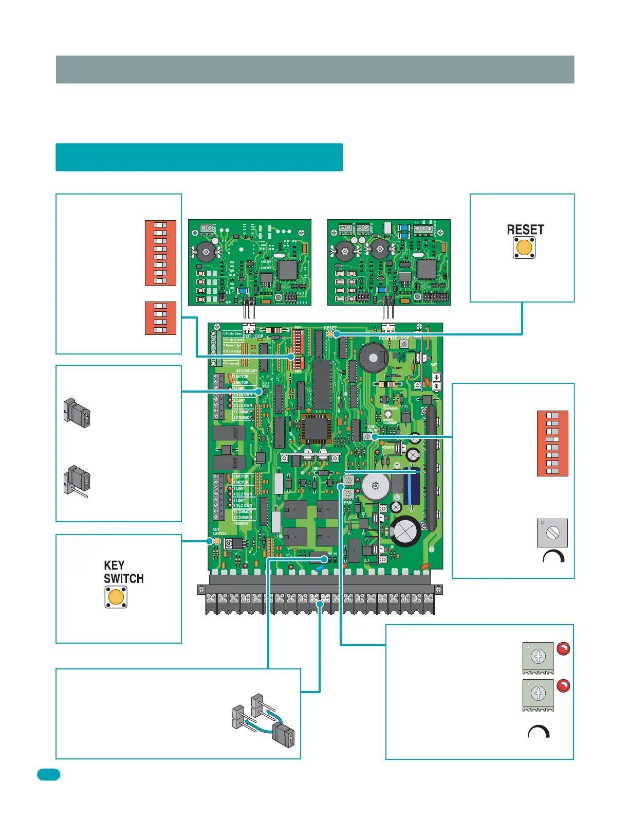
4.1 Circuit Board Adjustments
SECTION 4 - ADJUSTMENTS
The switch settings and adjustments in this section should be made after your installation and wiring to the operator(s) is
complete. Whenever any programming or switch setting on the control board are changed, press the reset switch for new
settings to take effect.
• Auto close
timer (when
turned on) SW 1,
switch 4.
Adjust from 1
second (full
counter
clockwise) to
approximately
23 seconds
(full clock-
wise).
Dry relay contacts (terminals 10-11) can
be set for Normally Open (NO) or
Normally Closed (NC) operation by
placing the relay shorting bar on the N.O.
or N.C. pins respectively.
Self test mode is
for bench checks
only. The operator
will continually
cycle the gate.
The jumper must
be set at normal
mode to function.
Press reset switch to
activate changed
control board settings.
Cycles the operator when
pressed.
1
ON
2 3 4 5 6 7 8
NO
NC
SW 1
TIME
DELAY
Self Test
Mode
Normal
Mode
123
Self Test
Key Switch
Auto Close Timer
Set DIP-switches
on the circuit board
to the desired
setting.
See switch-setting
charts on next 2
pages.
1
ON
2 3 4 5 6 7 8
SW 1
1
ON
2 3 4
SW 2
DIP-Switches
Dry Relay Contact
Adjust reversing sensitivity
for:
PRIMARY (single) and
SECONDARY (dual) operators.
See 4.4 on pages 32 and 33.
Secondary
Primary
Min Max
Sensitivity
Reverse Sensors
12345
6
7
89
10 11 12
13
14 15
16 17 18 19
20
Loop Detector Loop Detector
Reset Switch
9410 Single Channel 9409 Dual Channel
4302