6400-065-C-1-09
28
Reverse
Reverse
Shadow
Automatic Exit
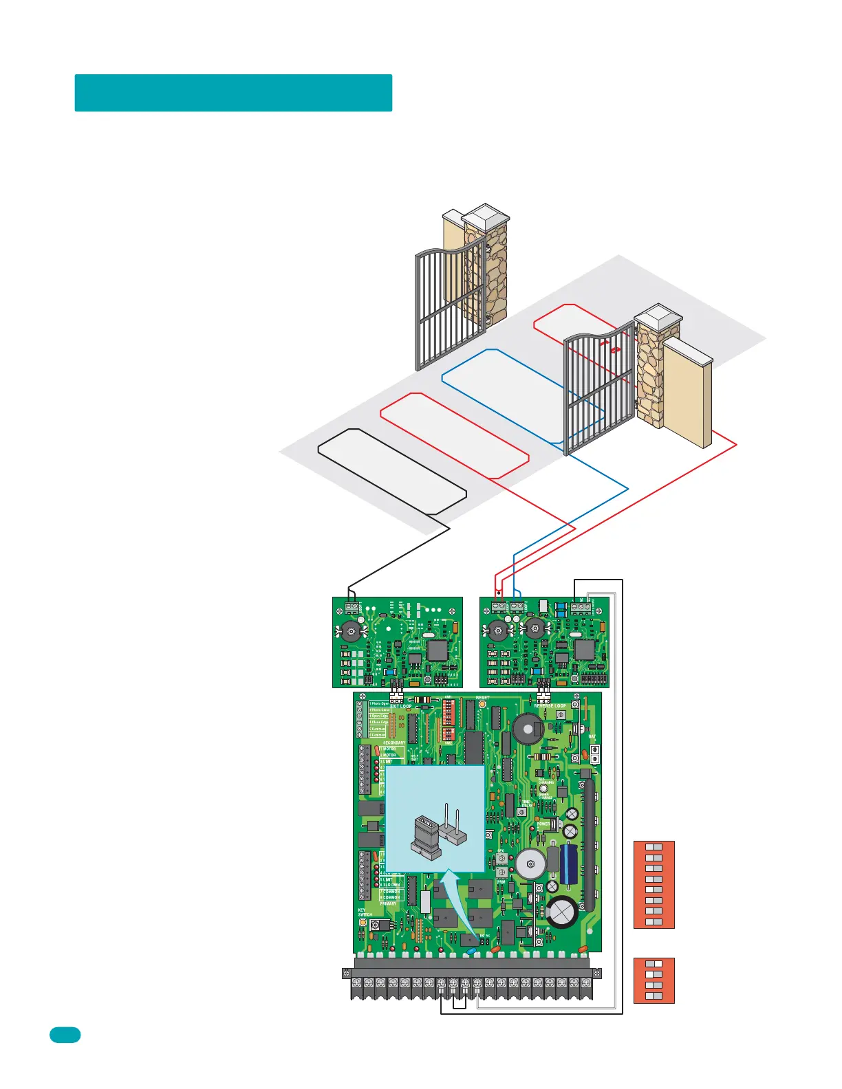
3.5 Loop Detector Wiring
To protect the operator from accidentally closing on vehicles in the gate’s path, DoorKing highly recommends that loops and
loop detectors be installed. Loops are laid underneath, cut into asphalt or concrete driveways or buried beneath gravel and earth
driveways. A loop detection system will sense a vehicle like a metal detector and send a signal to the gate operator preventing
the gate from automatically opening or closing on a vehicle when it is in the gate’s swing path. Refer to the separate loop and
loop detectors information manual (Loop Info G-3-02) for further information. DoorKing recommends that a licensed installer
perform this work.
Note: Loop detector wiring is shown
for DoorKing plug-in loop detectors
P/N 9409-010 and P/N 9410-010
only. If other loop detectors are
used, refer to the installation
instructions supplied with those
detectors for wiring instructions.
Automatic Exit Loop
Automatically opens the gate for exiting vehicles
without having to use a transmitter or keypad.
The exit loop can be placed 20-100 feet away
from the gate so that the gate is open or partially
open as you drive up to it.
Reverse Loops
Reverse loops are placed just outside the
gate’s swinging path to prevent the gate from
closing on a vehicle in these areas. They will
stop or reverse the cycling of the gate while a
vehicle is in or near the gate’s swing pathway.
Reverse loops are wired in series.
Shadow Loop
The shadow loop is placed inside the gate’s swinging
path to prevent the gate from closing on a vehicle in
this area. It is only active when the gate is in the full
open position. Vehicles in the shadow area will
activate it. It will not allow the gate to close unless this
area is clear. After a closing cycle begins, the shadow
loop will not reverse the gate. Reverse loops work in
conjunction with the shadow loop and both should be
used.
12345
6
7
89
10 11 12
13
14 15
16 17 18 19
20
9410
4302
9409
Com
N.O.
1
ON
2 3 4
SW 2
1
ON
2 3 4 5 6 7 8
SW 1
SW 1, switch 5
is OFF.
SW 2, switch 1
is ON and
switch 2 is OFF.
Shadow Loop Output
Shadow Loop
DIP-Switch Settings
Relay must be
set to N.O.
NC
NO