Operation Section
-100-
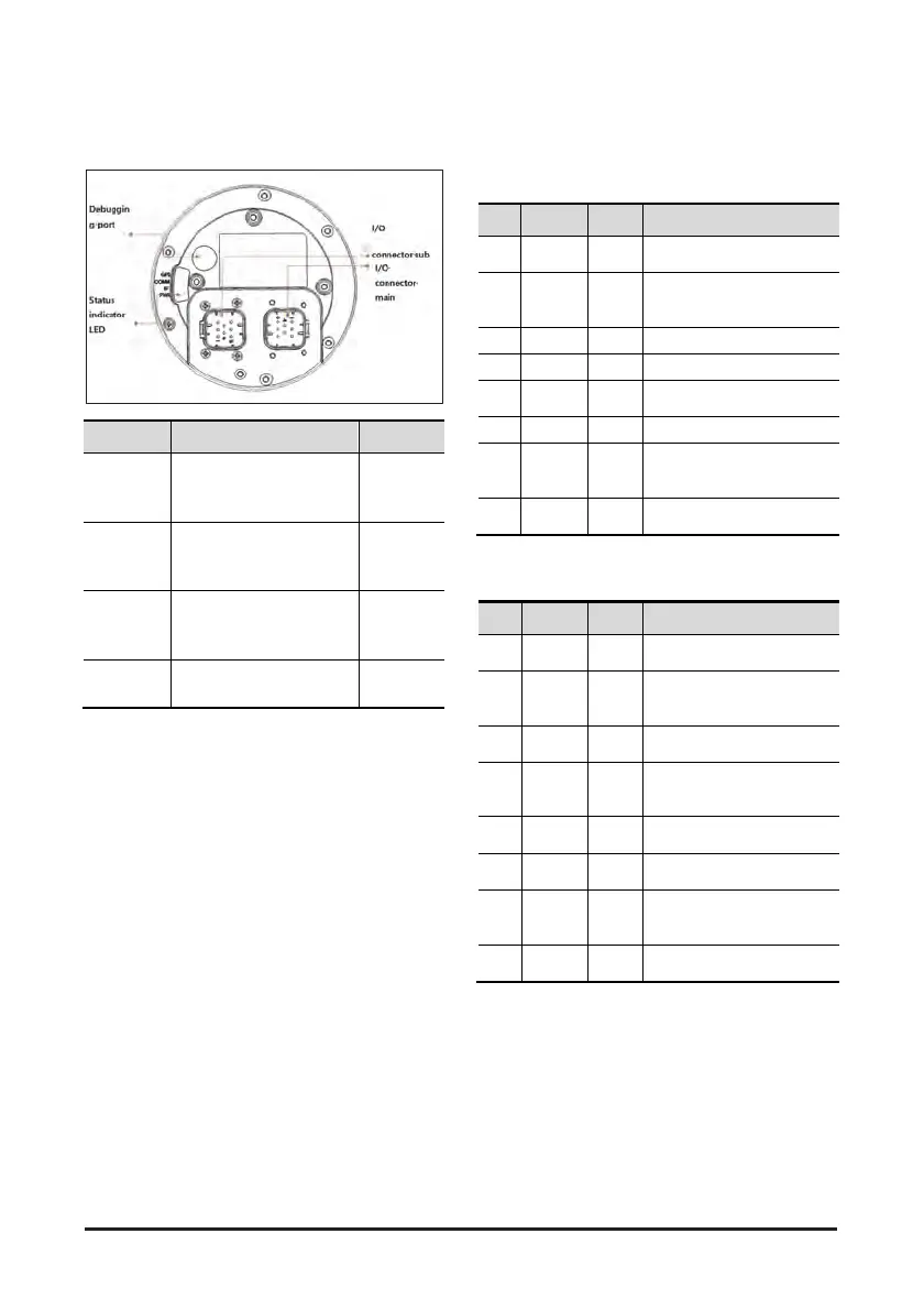
Names and Functions of Parts
Terminal Body
Name Feature Remarks
I/O
connector
main
A connector for
connecting to the
vehicle
8 pins,
black
I/O
connector
sub
A connector for
connecting to the
vehicle
8 pins,
natural
Status
indicator
LED
Four LEDs indicating the
current status of the
terminal
Debuggin
g port
Debugging port for
developers
There are two types of connectors: A (black) and B
(natural). The pin map is shown in the table below.
• CONNECTOR Main (776276-1, Black)
No. Name Type Description
1
FUEL_
ADC
Input
Signal Input Analog (with
ADC)
2
CAN
Low
Input
/Outp
ut
CAN Low Signal
3 IGN+ Input IGN+ Signal Input (Logic)
4 BRK Input Brake Signal Input (Logic)
5 GND1
Pow
er
Digital Ground
6 SPD Input Speed Signal Input (Logic)
7
CAN
High
Input
/Outp
ut
CAN High Signal
8 BAT+
Pow
er
Car Battery +
• CONNECTOR Sub (776276-2, Natural)
No. Name Type Description
1
ACC_
TXD
Outp
ut
RS232C Level TXD Signal
(Acc_Sensor)
2 GPI01
Input
/Outp
ut
Digital Signal
Input1/Output1 (Logic)
3
NFC_
TXD
Outp
ut
RS232C Level TXD Signal
(NFC Reader)
4 GPI02
Input
/Outp
ut
Digital Signal
Input2/Output2 (Logic)
5 GND2
Pow
er
Digital Ground
6
ACC_
RXD
Input
RS232C Level RXD
Signal (Acc_Sensor)
7 GPI03
Input
/Outp
ut
Digital Signal
Input3/Output3 (Logic)
8
NFC_
RXD
Input
RS232C Level RXD
Signal (NFC Reader)