Service Manual
Ophthalmic Surgical System
Chapter 2 - Maintenance instructions
26 - Version date: Nov. 01, 2013 - N° doc.: 30204400-B
2.7.11 Laser: replacing module
This paragraph describes the disassembly of the Laser module. Assembling is carried out in
the opposite way.
1. Remove the drawer as described in par. ’Drawer’, page 15).
2. Remove the back cover as described in par. ’Back Cover’, page 15).
3. Remove the top cover as described in par. ’Top Cover’, page 16).
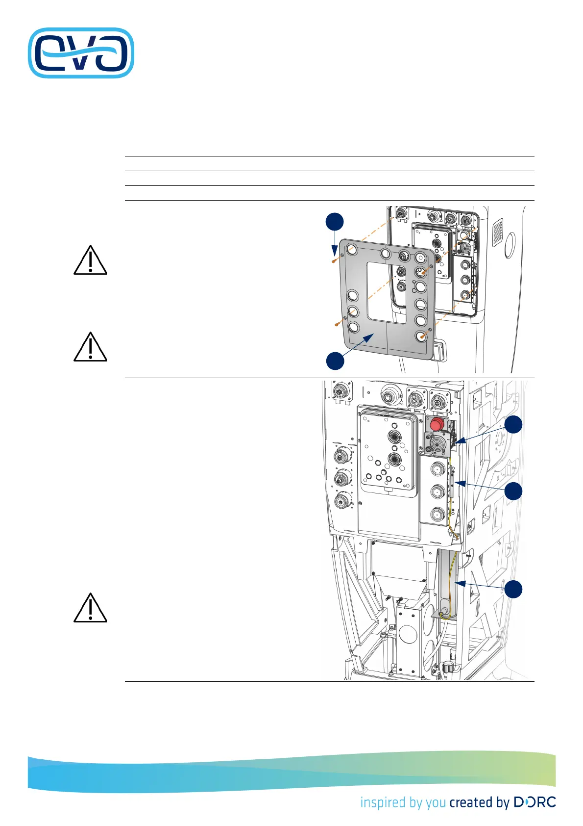
4. Unscrew the 4 screws of the interface
plate.
5. Remove the interface plate.
Be careful! There is a the
cable b
etween the interface
plate and the EVA located below
the posterior module.
6. Disconnect the cable connectors (not visi-
ble in the picture).
At assembling, first connect the
cable connectors.
This picture shows the cable routing of the
laser fiber, seen from the front side, however
the front panel and side panels are not disas-
sembled; only the interface plate has to be
removed.
This picture helps you to find the fiber and also
to show you how to replace the fiber into the
correct position.
The fiber is connected to the interface panel
[A] and the laser module [C]. Close to the Illu-
mination module the cable is fixed behind a
guide plate [B].
The laser fiber is very fragile.
Handle the fiber with care.
Carefully remove and replace the
modules.