Electrical connections
14
Installing fieldbus communication on the transmitter
— The transmitter can be connected to a certified intrinsically safe fieldbus system,
which supports FISCO (Fieldbus intrinsically safe concept).
— The PROFIBUS PA transmission technology for intrinsically safe applications is
MBP. MBP stands for:
– Manchester Coding (M)
– Bus Powered (BP)
— 5 transmitters can be connected to a segment with a typical segment current
of 100 mA.
● Install the 2-wire connection cable in the cable gland, cut it to length and strip off
the insulation (approx. 80 mm).
● Shorten the shield (if installed) to prevent short-circuiting.
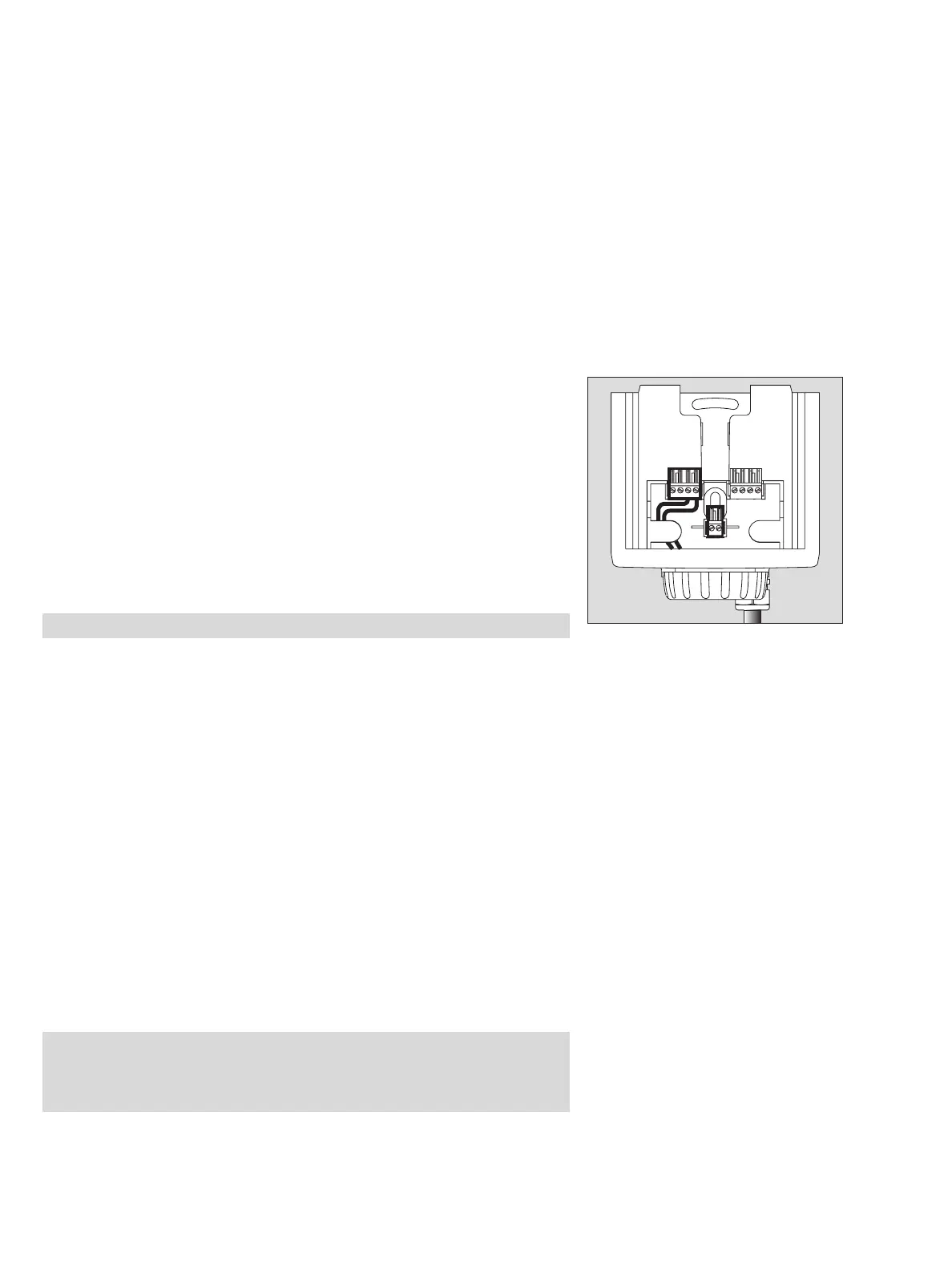
● Connect cable:
1 Use a 4-pole terminal block (X7), Part No. 83 16 268, for the
Dräger Polytron 7000 – Observe the polarity of the connections. Cut excess
wires short or
2 secure them in center terminals (Part No. 83 16 422).
1 Slide connecting terminal back into holder.
● Secure cable in holder.
● Fold up the installation notes and place them in the Dräger docking station for
future use during commissioning.
● Refit raincover (protection against dust and splashing water).
Installing the transmitter in areas subject to explosion hazards of
Zone 0 or Zone 1:
● Only safety barriers with the following characteristics may be used:
U
max
≤24 V, I
max
≤0.38 A, P
max
≤5.32 W or those which correspond to the
FISCO model.
— The transmitter may only be connected in 2-wire connection to the left
4-fold terminal block (X7) of the docking station. No electrical connections may be
made to the right 4-fold terminal block (X8).
Installing the transmitter in areas subject to explosion hazards of Zone 2:
— Make sure that the supply unit corresponds with the FINCO model and that the
maximum permissible capacitance and inductance of connections to the supply
unit are not exceeded, (also take the cable into account).
— The safety-related input parameters of the transmitter are:
C
i
= 5 nF, L
i
= 10 μH.
— The transmitter may only be connected in 2-wire connection to the left
4-fold terminal block (X7) of the docking station. No electrical connections may be
made to the right 4-fold terminal block (X8).
Caution: Insert 4-pole (X7) terminal block into left holder.
Caution: The category 1 marking has to be cut out from the rating-plate label.
Once the unit has been used after installation in the above manner, it may
never be installed in explosion-hazard areas of Zone 0 or Zone 1
(device category 1 or 2). Explosion hazard!
01023758_4.eps
1
X7 X8
2
FB –
FB +