13
Electrical connections
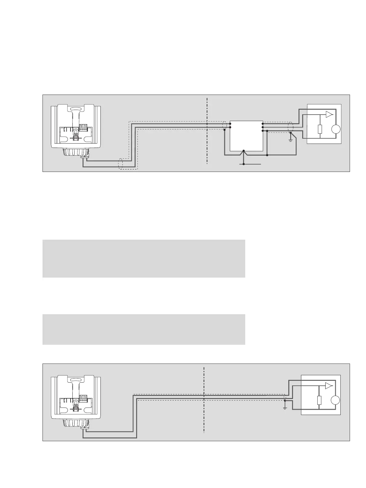
● The maximum possible cable lengths can be found in the table on page 18. In
each case, use the line marked "Number of transmitters = 1".
— Connect shielding to earth point and/or 0 V (Ex i).
Installing the transmitters in explosion-hazard areas of zone 2 or 22 without a
safety barrier
— Use only supply units of the device category 3.
— Take care that the maximum permissible capacitance and inductance of connec-
tions to the supply unit are not exceeded, also taking the cable into account.
The safety-related input parameters of the transmitter are:
C
i
= 5 nF, L
i
= 50 μH.
● The maximum possible cable lengths can be found in the table on page 19. In this
table, select the line, " Number of transmitters = 1".
Installing the transmitters in non-explosion-hazard areas:
● The maximum possible cable lengths can be found in the table on page 19. In this
table, select the line, " Number of transmitters = 1".
Caution:
The category 1 marking has to be cut out from the rating-plate label. Once the
unit has been used after installation in the above manner, it may never
be installed in explosion-hazard areas of zone 0 or zone 1 (device category 1
or 2). Explosion hazard!
Caution:
The explosion-protection markings has to be removed from the transmitter.
Once the transmitter has been used after installation in this manner, it may
never be installed in explosion-hazard areas.
00923758_1_en .eps
Non-explosion-hazard areaExplosion-hazard area, zone 0, 1 or Div. 1
Safety barrier
Control unit
Ex i
PA
Earth point
4 ... 20 mA
0 V
+
–
+
4 to 20 mA
+24 V
00823758_1_en.eps
Non-explosion-hazard area
without a safety barrier
Control unit
4 ... 20 mA
0 V
+
–
+
4 to 20 mA
+24 V
Explosion-hazard area, zone 2 or non-explosion hazard