38 Dräger PSS
®
Merlin
®
Appendix C – PSS
®
AirBoss Connect
Appendix C – Appendix C – PSS
®
AirBoss Connect
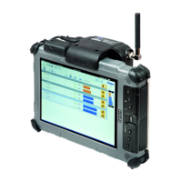
The Dräger Connect ECU is a battery powered integrated electronic monitoring system used on Dräger breathing apparatus. The
system provides visual and audible information about the status of the breathing apparatus, and has an integral DSU. Visual
information is provided on the LCD screen, and by LEDs in the LED panel of the Connect ECU UI module and in the buddy
beacons in the backplate. Audible signals are emitted from an electronic sounder in the Connect ECU UI module.
See the PSS
®
AirBoss Connect instructions for use for more information.
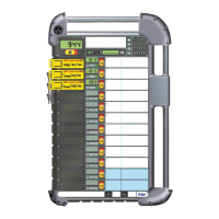
C.1 Tally
Connect ECU may be supplied with tallies. A label on the tally shows the brigade name, the electronic monitoring unit
identification number and three headings that allow the following information to be added using a suitable waterproof marker:
The name of the wearer.
The cylinder pressure on activation of the Connect ECU.
The actual entry time into the risk area (using the clock of the Entry Control Board).
Where a radiation risk may be present, a dosimeter reading can be recorded on the reverse side of the tally (prior to entry and
after exit).
The tally can be assembled on to the key ring of the key of the associated Connect ECU.
C.2 In Use
C.2.1 Radio Contact (Entry Control Board – Connect ECU)
When the tally is inserted into any of the available channels of the Entry Control Board, the ECB identifies the associated Connect
ECU and the digital communication link is activated (logon). Upon a successful logon, the active communication icon displays
on the Connect ECU UI module screen for approximately two seconds and a double beep tone is emitted.
As long as the communication link is maintained (logged on and in range), the active communication icon displays briefly.
C.2.2 Evacuation Signal from ECB to Connect ECU
When the ECO instigates an evacuation signal, the Connect ECU UI module emits a repeating audible beep alarm and the
evacuation request received icon is displayed.
Acknowledge the evacuation request by pressing the RH button of the Connect ECU UI module. The evacuation confirmation
has been sent icon is briefly displayed before the Connect ECU UI module returns to the normal operating screen.
Evacuate immediately to the control point.
C.2.3 Voluntary Withdrawal Signal from Connect ECU to ECB
Press and hold the RH button of the Connect ECU UI until the send voluntary withdrawal request icon displays, and then
release the button. The voluntary withdrawal signal is sent to the ECB and the waiting for response icon is displayed.
On acknowledgement from the ECO the Connect ECU UI module emits a short audible alarm and the withdrawal request
confirmed icon displays. When the alarm stops, the Connect ECU UI module display returns to the normal operating screen.
C.2.4 Loss of Radio Contact (Entry Control Board – Connect ECU)
If there is a loss of radio contact between the ECB and the Connect ECU, the out of range icon displays briefly every two
seconds accompanied by an audible beep tone.
When radio contact is re-established, the active communication icon displays on the Connect ECU UI module screen briefly
and a long tone is emitted. The Connect ECU UI module returns to the normal operating mode.
C.2.5 Connect ECU fault
If the error occurred icon displays, there is a fault with the telemetry system. The icon may display when the Connect ECU
starts, or at any time during use.
Refer to the troubleshooting information (Section 7.6 on Page 27) for further details and possible remedy information.